Explore product updates, engineering guides, application insights, and exhibition news from Heymed Medical, covering medical cable assemblies, EEG electrodes, neurostimulation accessories, and OEM/ODM development.
A customer developing an EEG or biosignal device may already have a suitable ear clip but need a different connector, pinout, cable length or wire construction. In other projects, the electrical interface is already defined while the electrode and cable assembly still need to be developed.
In both cases, an Ag/AgCl ear clip electrode should be reviewed as one complete interface rather than as a clip and cable selected separately.
Contact geometry, clip mechanics, connector mating, pin assignment, cable construction, shielding and strain relief all influence whether the final assembly can be integrated reliably with the host system.
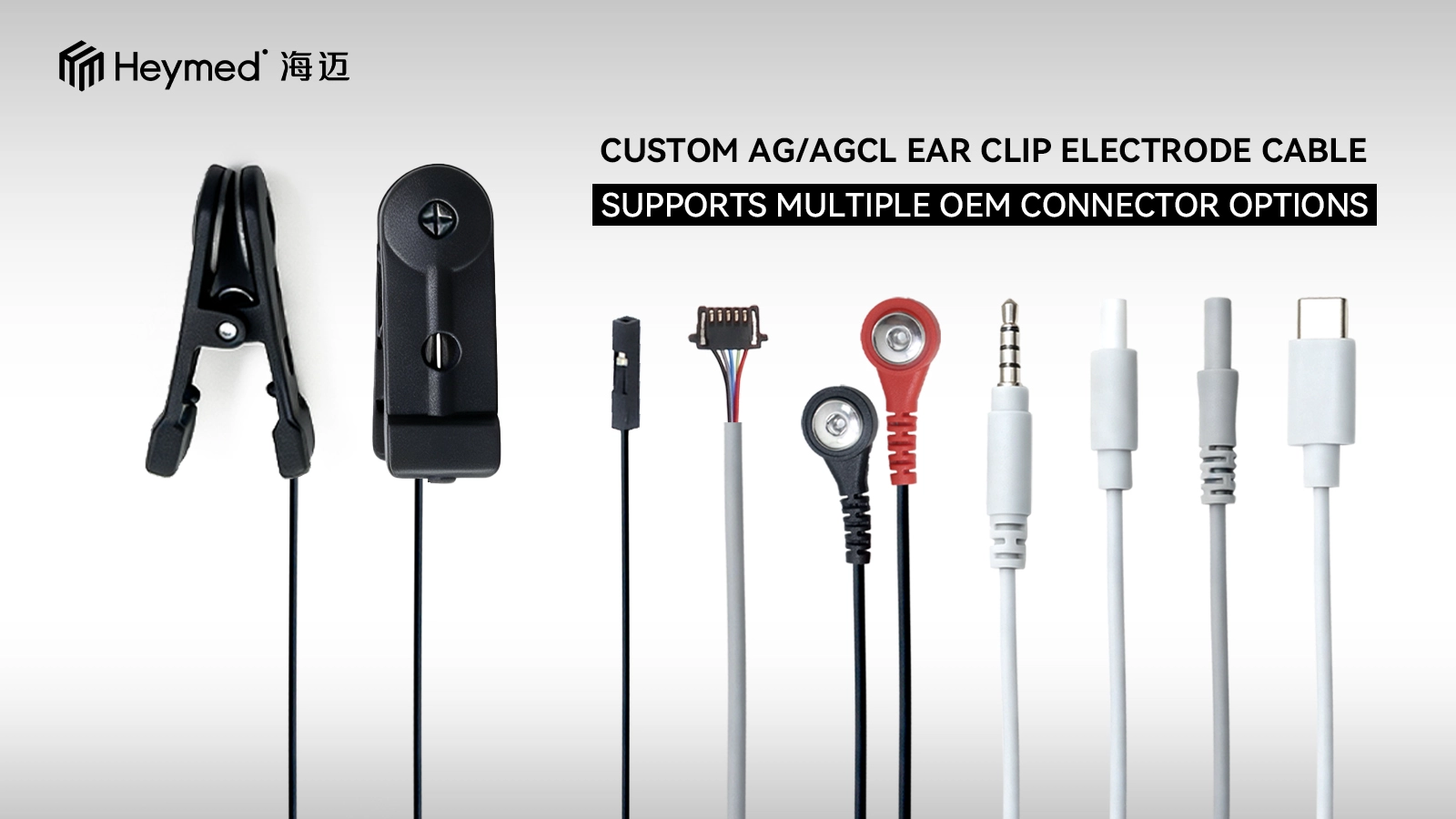
Heymed Medical develops custom Ag/AgCl ear clip electrode cables for EEG, biosignal acquisition, research and compatible device-integration projects, with configurations developed according to the customer's device interface and approved specification.
The first engineering question should be how the electrode is defined within the host system.
Depending on the acquisition architecture, an ear clip may be assigned as a reference, ground, bias or another system-defined signal connection. The function cannot be determined from the appearance of the clip alone.
Before selecting the connector or preparing samples, product teams should therefore confirm:
This is particularly important when replacing an existing cable. Two connectors can look identical while using different terminal positions or internal wiring.
A connector drawing, pinout, device-side specification or working sample provides a more reliable basis for engineering review than appearance alone.
The conductive contact is one of the main design elements of an ear clip electrode.
For Ag/AgCl ear clip projects, the engineering specification should define the required contact arrangement, contact dimensions and how the conductive element is integrated with the clip.
The intended ear-contact position also affects contact geometry. Contact size, surface shape, clip direction and cable pull need to be considered together rather than independently.
For projects based on an existing product, a physical sample or clear dimensional reference can help determine which parts of the structure can be retained and which require modification.
An ear clip must provide repeatable positioning while remaining compatible with the required contact location and cable direction.
Development review may include:
Increasing clamping force alone does not necessarily improve the design. Contact area, mechanical geometry and cable pull should be evaluated together.
For an OEM electrode assembly, the connector is part of the electrical and mechanical interface.
Heymed Medical can review 2.54 mm board connectors, compact circular connectors, audio-style interfaces, locking connectors, overmolded connectors and customer-specified interfaces according to project requirements.
However, a connector name or appearance does not confirm compatibility.
The final connector should be selected according to the mating dimensions, available device space, terminal definition, pinout and expected cable orientation.
When a proprietary signal is carried through a connector normally associated with another interface, the electrical definition should be clearly documented in the project drawing.
Cable length is only one part of the cable specification.
Depending on the device architecture, the engineering team may also need to review conductor configuration, core count, flexibility, shielding, jacket material, branch construction, color identification and strain relief.
Shielding should be selected according to the signal architecture and device requirements rather than added automatically.
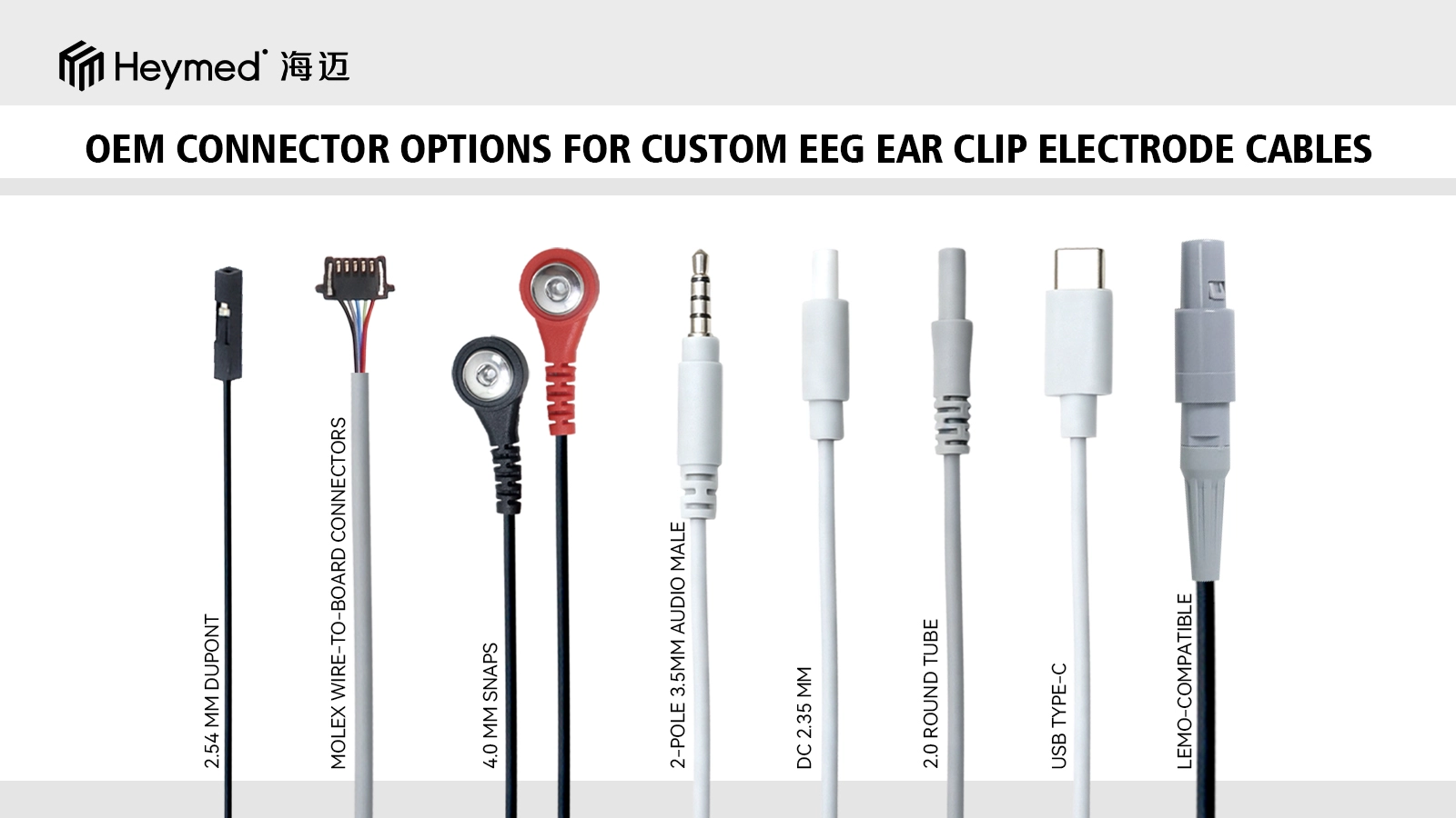
A custom Ag/AgCl ear clip electrode project may include changes to the conductive contact arrangement, ear clip structure, connector, pinout, cable length, conductor configuration, shielding, cable jacket, strain relief, color, marking and packaging.
The final configuration should always be released against the approved device requirements and project specification rather than a general catalog description.
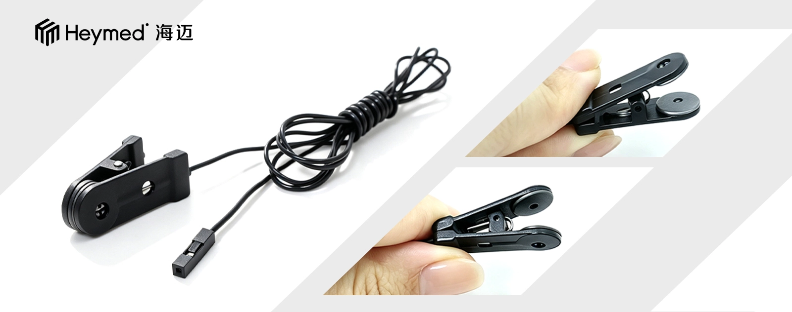
Heymed Medical's existing Ag/AgCl ear clip electrode cable can also be used as an engineering reference when a project requires a different connector, cable or device-side interface.
A complete production drawing is not required before the first discussion.
An initial review can usually begin with a product photo, reference sample, connector information and basic device requirements.
A typical development sequence is:
This approach allows the electrode, connector and cable to be developed as one assembly instead of modifying individual components independently.
The first engineering sample should be used to confirm both device compatibility and manufacturing requirements.
Ear contact
Confirm that the conductive contact reaches the intended position and that the ear clip can be applied and removed as expected.
Electrical connection
Check continuity, pinout, polarity and channel assignment against the approved device information.
Connector fit
Verify mating, orientation and retention with the actual device or approved mating connector.
Cable handling
Review flexibility, cable length, strain relief and whether cable routing places unnecessary load on the ear clip.
Identification
Confirm channel, left/right identification, labeling, product code and packaging information before the specification is released.
Inspection requirements should be defined according to the product design and identified project risks.
Depending on the configuration, inspection may include appearance and dimensional checks, continuity, polarity, connector fit, resistance checks, pull-force verification or cable-flex testing.
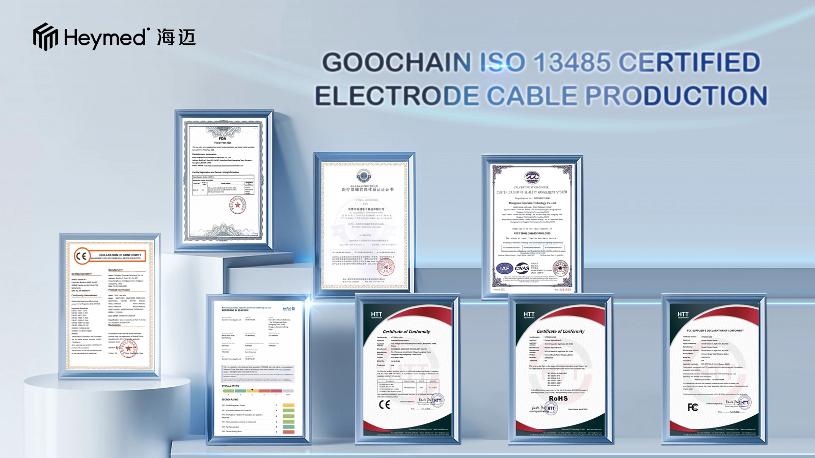
Heymed Medical supports engineering review, prototyping, inspection and controlled production under its ISO 13485 quality management system.
ISO 13485 refers to the manufacturer's quality management system and should not be interpreted as automatic approval of an individual electrode, cable or finished medical device. Product-level regulatory requirements depend on the final device, intended use, classification, legal manufacturer and target market.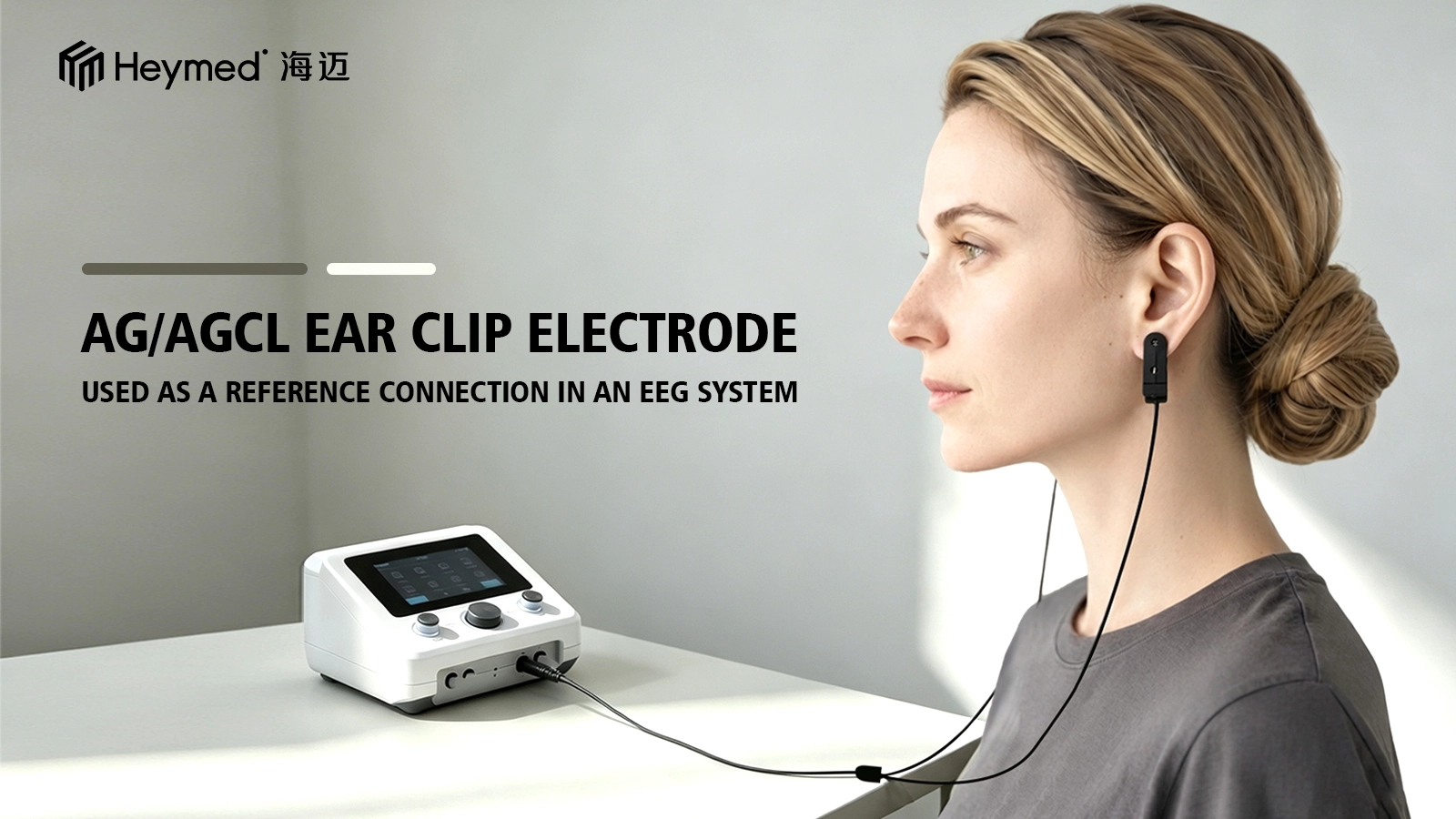
For a more efficient engineering review, provide the following information where available:
If some details are still open, the project can begin with a product image and device-interface information. The engineering team can then identify the items that need to be confirmed before sampling.
Can an existing Ag/AgCl ear clip design be modified with another connector?
Yes, subject to engineering feasibility. The clip structure may be retained while the connector, pinout, cable length or cable construction is modified. The mating interface and electrical definition should be confirmed before sampling.
Can the same ear clip electrode be used with several devices?
Possibly, but each device should be checked separately for connector mating, pinout, electrical definition and mechanical compatibility.
Do you support prototype samples before volume production?
Yes. Engineering samples can be prepared to evaluate structure, connector fit, electrical continuity and cable configuration before the final production specification is released.
Send Heymed Medical your device interface, connector or pinout information and a reference drawing, photo or sample.
Our engineering team can review the electrode contact, clip structure, cable assembly and connector requirements as one complete interface before sampling.
Work with Heymed Medical on OEM/ODM development and controlled manufacturing for tVNS and taVNS products, EEG electrodes, medical lead wires, custom cable assemblies, and medical docking and charging products—from engineering samples and validation to volume production.
Tell our engineering team about your product application, device interface, performance targets, compliance needs, and expected quantity. We will review your information and contact you to discuss technical feasibility, customization options, and recommended next steps.
Tip: A drawing, device interface photo, pinout diagram, or reference sample can help our engineering team evaluate your project more accurately and efficiently.
 Search