Explore product updates, engineering guides, application insights, and exhibition news from Heymed Medical, covering medical cable assemblies, EEG electrodes, neurostimulation accessories, and OEM/ODM development.
A plug that inserts into the device is not yet proof that an ear electrode cable is compatible. Mechanical mating and electrical definition are two separate checks.
For OEM buyers and engineering teams, the connector housing, diameter or pitch may match while the internal pin assignment, polarity, channel definition or electrode mapping is different. This is why a replacement cable should be verified against the host device before the sample is approved.
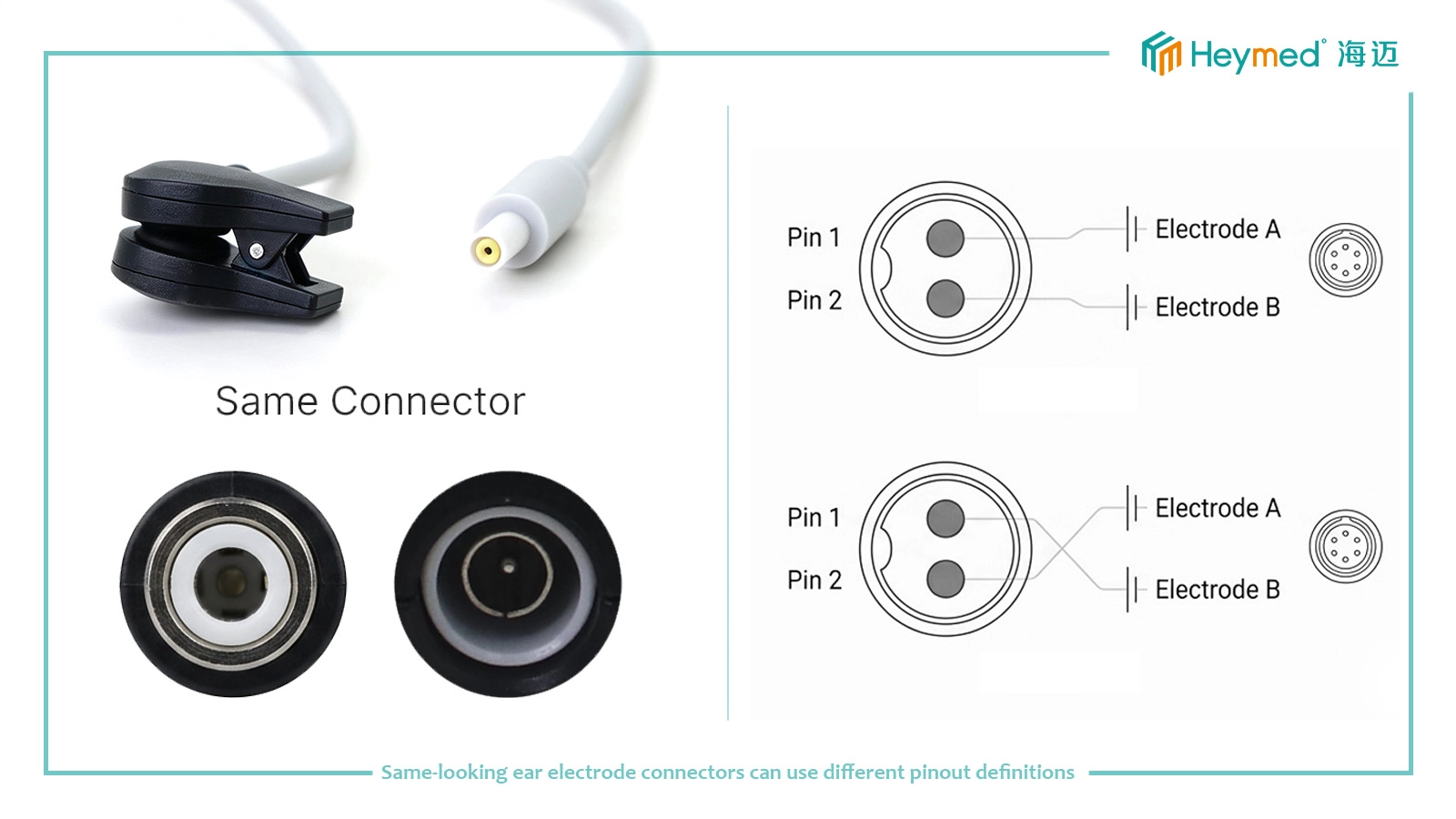
A visual match can help identify the connector family, approximate size and mating style. It cannot confirm what each internal terminal is connected to. A cable can therefore fit mechanically and still be wired incorrectly for the target controller or acquisition module.
| Check Item | Can Appearance Help? | Still Needs Verification? |
|---|---|---|
| Connector family / nominal size | Often yes | No |
| Mechanical mating / physical fit | Can be checked | Does not prove wiring |
| Pin assignment | No | Must be verified |
| Polarity or channel mapping | No | Must be verified |
| Which pin reaches which electrode | No | Must be verified |
| Compatibility with another device | No | Requires device-specific confirmation |
For procurement teams, this distinction is important when replacing an existing accessory. “The plug looks the same” is useful as a starting point, but it should never be the final approval criterion.
Heymed Medical offers a DC 2.35mm conductive silicone tVNS / taVNS ear electrode cable and a DC 2.35mm dual Ag/AgCl ear clip electrode cable. Both use a DC 2.35mm device-side interface, but the electrode structures are different and the electrical mapping still needs to follow the target device definition.
The connector diameter alone does not define polarity, internal contact assignment or the relationship between the device-side contacts and the ear electrodes. Two controllers can use mechanically similar 2.35mm connectors while assigning the electrical contacts differently.
Before sampling, confirm the host-device pin definition, the required electrode mapping and the intended polarity or channel relationship. If the project is a replacement cable, an approved working sample can also be used as a comparison reference.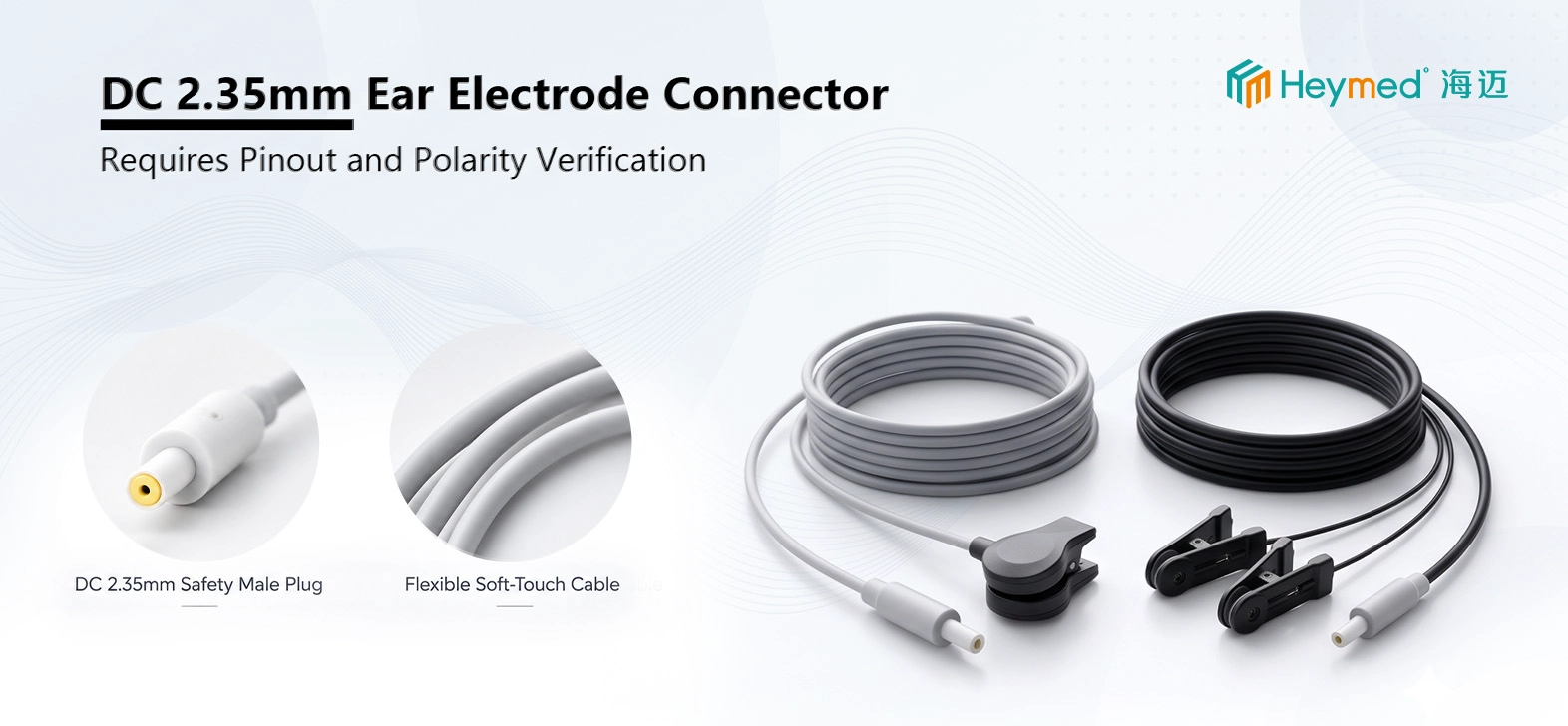
The 2.54mm Dupont to Ag/AgCl ear clip electrode cable is another good example. “2.54mm Dupont” describes an interface family, but an OEM project still needs to define connector gender, number of positions, housing orientation, wire sequence and signal assignment.
A male and female connector obviously cannot be treated as the same part, but even two connectors of the same gender and pitch may use a different wire order. The viewing direction of the pinout drawing also matters: a drawing shown from the mating face can appear reversed when compared with the wire-entry side.
For biosignal and prototype systems, do not infer channel function from wire color unless the color-to-channel mapping is controlled in the approved drawing or specification.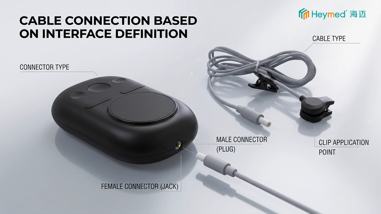
The first sample should be checked as an electrical mapping reference, not only as an appearance sample. A useful verification sequence is to confirm connector fit, then check continuity from each device-side terminal to the intended electrode contact or branch.
Continuity testing alone is not enough if the wrong pin is connected to the wrong electrode. The test result must be compared with the approved wiring definition.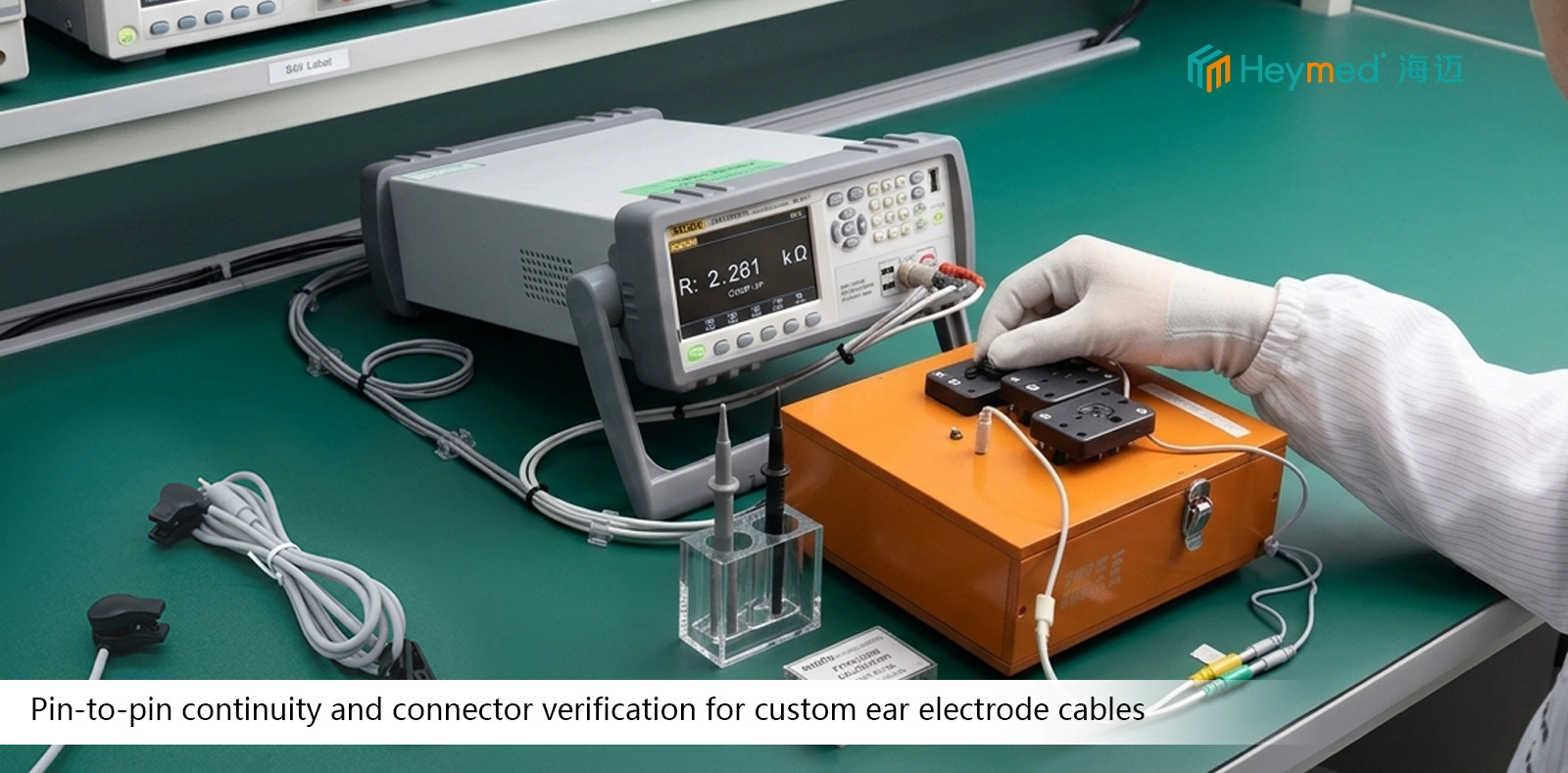
| Common Assumption | Why It Is Risky | Better Confirmation Method |
|---|---|---|
| “The plug fits, so it is compatible.” | Mechanical fit does not confirm electrical mapping. | Verify pinout and pin-to-electrode continuity. |
| “DC 2.35mm means the wiring is standard.” | The connector diameter does not define contact assignment. | Use the host-device pin definition. |
| “The wire colors tell us polarity.” | Color conventions can vary by project. | Use controlled drawings or channel labels. |
| “Continuity passed, so the cable is correct.” | A cable can be continuous but mapped to the wrong terminal. | Compare continuity results against the approved wiring table. |
| “It works on one device with the same plug, so it is universal.” | Another device can use a different pinout or channel definition. | Verify each target device separately. |
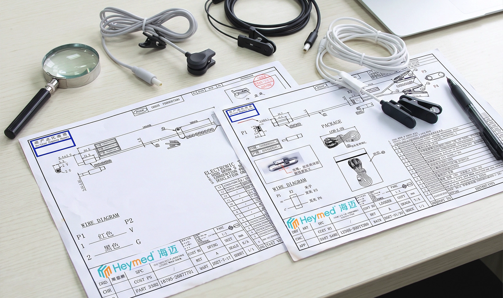
Do not guess the wiring from the connector appearance. If the pinout is not available, the project can begin with the host device, connector photo, PCB information, a known working cable or an existing sample. The engineering team can then identify what information must be confirmed before the sample is released.
For projects that include additional adapters, harnesses or device-side cable assemblies, Heymed Medical can also review the interface as part of a broader OEM/ODM medical product development project.
Yes. The connector housing or nominal size only describes the mechanical interface. Internal terminal assignment can still be different between devices or projects.
Only when the color definition is controlled by the approved drawing or specification. Wire color by itself should not be treated as a universal electrical standard.
Usually not reliably. A photo can help identify connector type and orientation, but electrical mapping should come from a pinout, wiring diagram, PCB definition or verified working sample.
Not without verification. Connector fit, pinout, polarity, channel definition and electrode mapping should be checked for each target device.
A working sample, host-device connector information, pinout or wiring definition, cable length and the required electrode configuration provide the strongest starting point.
Send Heymed Medical the host-device connector information, pinout or wiring diagram, reference cable, and required electrode configuration. Our engineering team can review the mechanical interface and electrical mapping together before sampling.
Work with Heymed Medical on OEM/ODM development and controlled manufacturing for tVNS and taVNS products, EEG electrodes, medical lead wires, custom cable assemblies, and medical docking and charging products—from engineering samples and validation to volume production.
Tell our engineering team about your product application, device interface, performance targets, compliance needs, and expected quantity. We will review your information and contact you to discuss technical feasibility, customization options, and recommended next steps.
Tip: A drawing, device interface photo, pinout diagram, or reference sample can help our engineering team evaluate your project more accurately and efficiently.
 Search