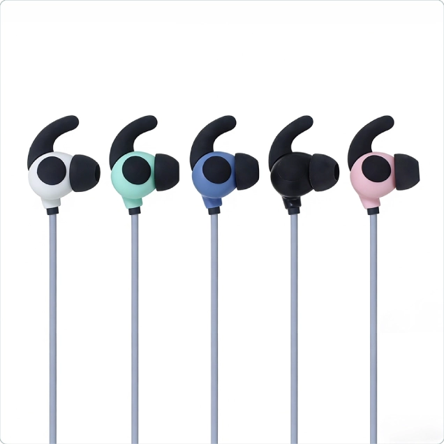
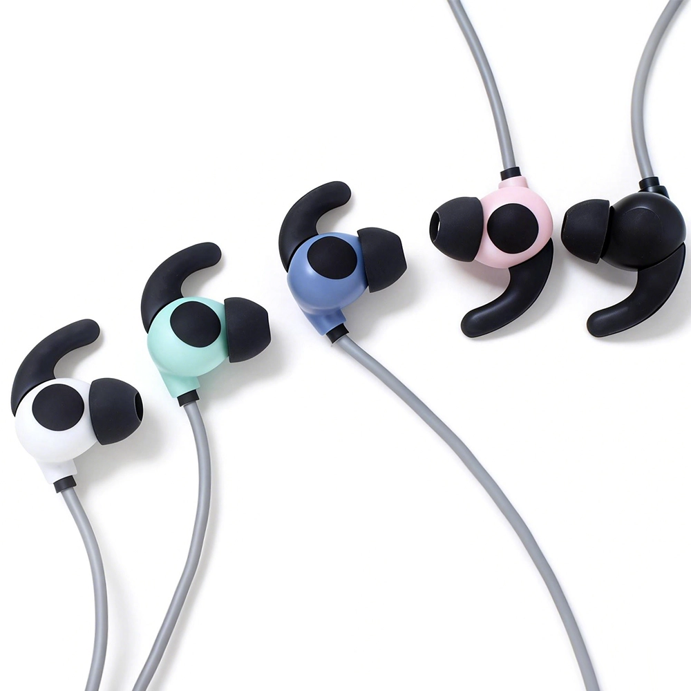
DC 2.35mm Two-Pole Conductive Silicone Ear Electrode Cable for tVNS / taVNS Devices
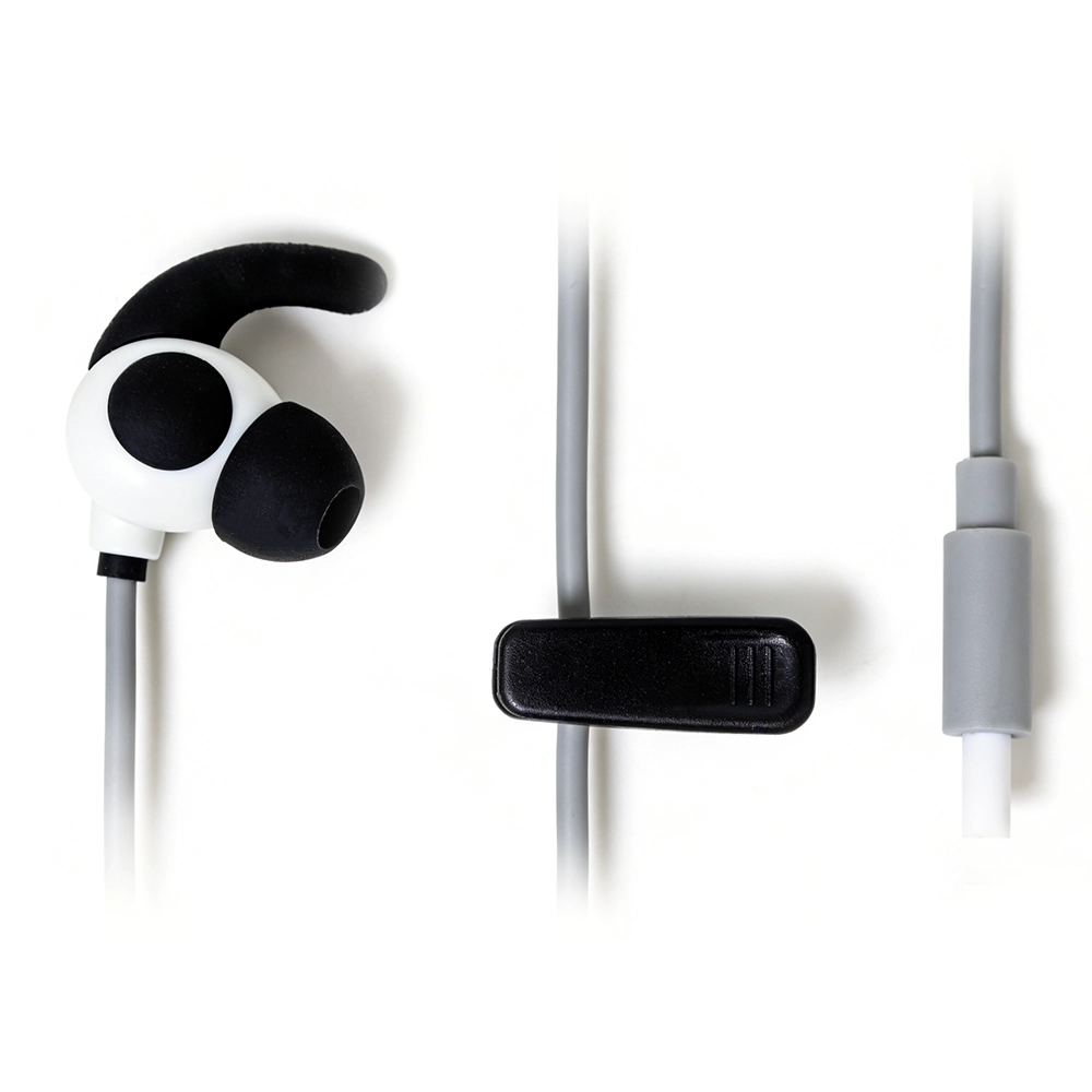
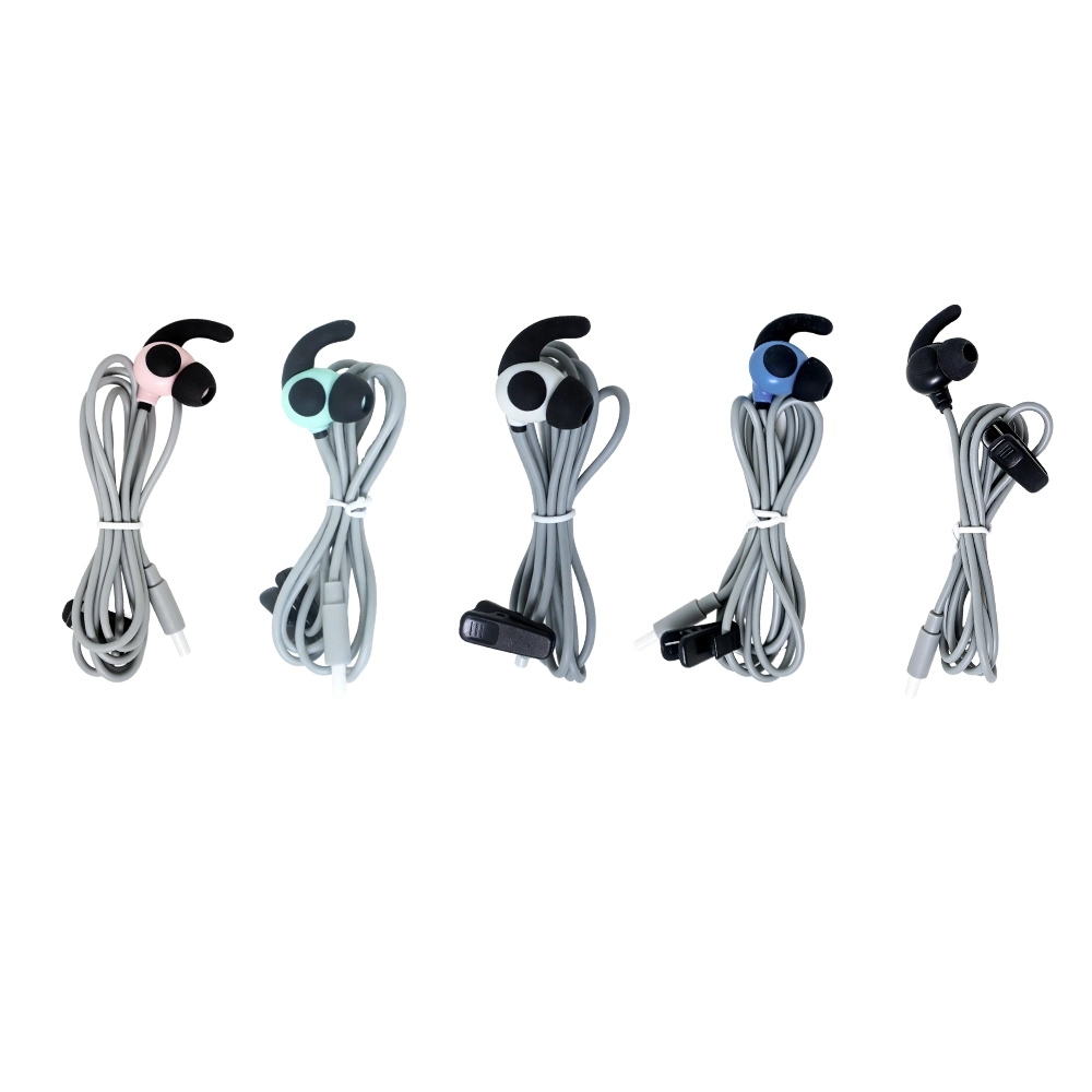
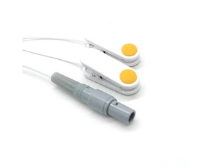
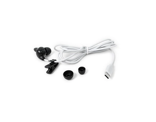
This reusable ear electrode cable combines a DC 2.35mm male device connector with a compact two-pole conductive silicone ear-contact structure. The assembly acts as a passive connection between compatible tVNS / taVNS equipment and the external auricular electrode interface.
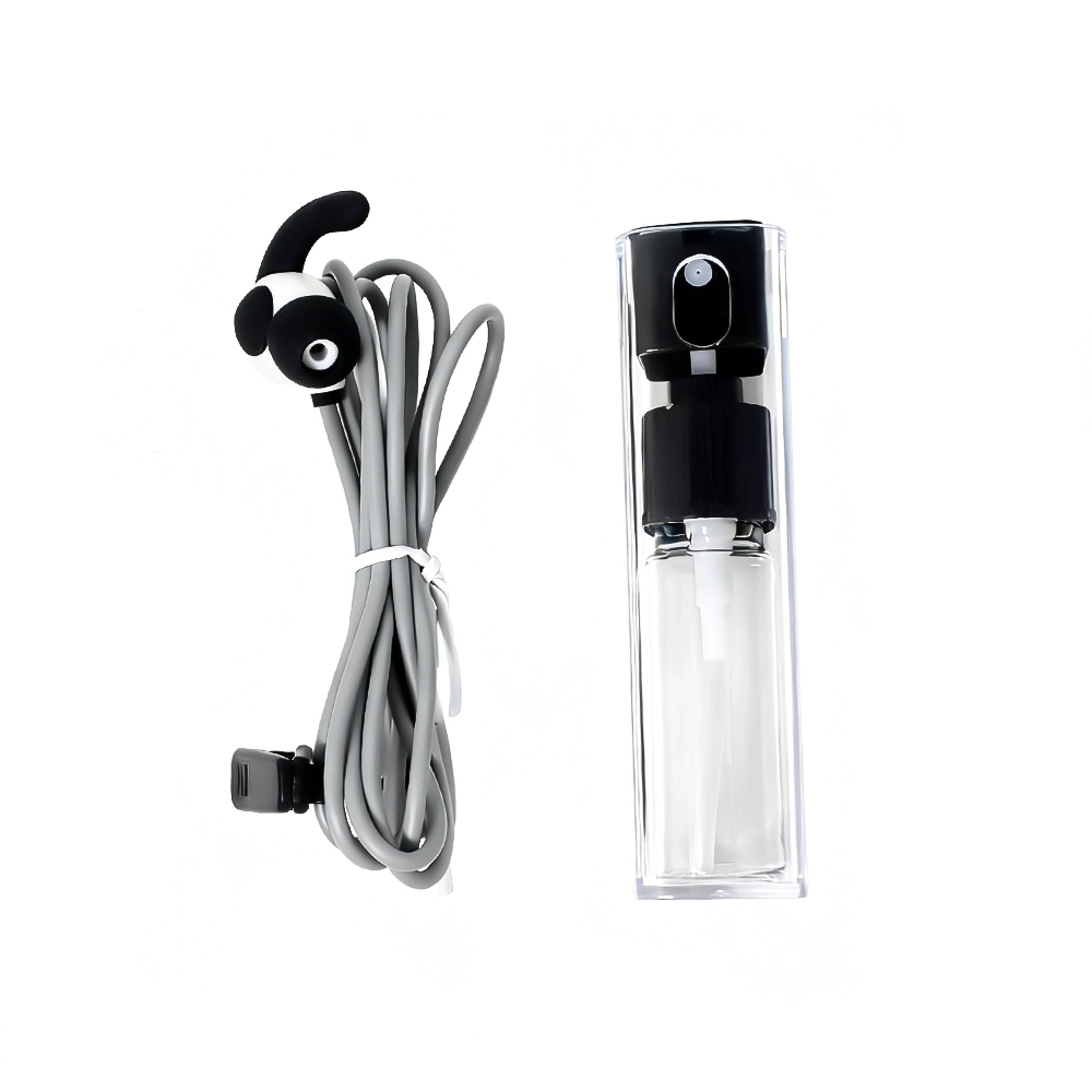
The standard configuration uses a 1.2m lead wire with molded strain relief. Connector pinout, polarity, cable length, jacket color, electrode geometry, labeling and packaging can be adapted according to the approved host-device interface and OEM/ODM project requirements.

Integrated Two-Pole Conductive Silicone Electrode Structure
The ear-contact component incorporates two separate conductive silicone contact areas within one compact electrode structure. This allows two electrical contact poles to be integrated into a single reusable ear-worn assembly while keeping the cable and contact geometry organized around the device interface.
The electrical role of the two contacts is defined by the connected controller. Polarity, output assignment and intended electrode position should therefore follow the approved product specification rather than being inferred from the physical shape of the electrode.
For projects requiring a different silicone clip architecture or alternative contact materials, our Reusable Silicone tVNS / taVNS Ear Clip Electrode Cable provides another development direction with configurable contact and connector options.
DC 2.35mm Interface Designed Around the Host Device
The standard device-side connection uses a DC 2.35mm male safety-style connector. While this provides a compact physical interface, the connector diameter alone does not establish electrical compatibility with another device.
Internal contact assignment, polarity and the electrical relationship between the connector and the two conductive silicone contacts must match the target controller. Two devices using mechanically similar 2.35mm connectors may still use different electrical definitions.
Where a locking equipment interface is preferred, the same general device-to-ear-electrode concept can be developed with a 4-Pin Self-Locking Connector to Dual tVNS Ear Clip Electrode Cable as an alternative connection architecture.

Ear-Contact Geometry Should Match the Finished Product
Ear electrode geometry influences how the conductive contacts are positioned relative to the intended auricular contact area. Contact dimensions, spacing, electrode-body shape and cable exit direction should therefore be reviewed together with the mechanical design of the finished device.
For OEM/ODM programs, the electrode structure can be evaluated from customer drawings, existing samples, industrial-design files or device-interface requirements. This allows mechanical fit and electrical connection to be considered before prototype production.
Additional ear-contact and cable structures can be reviewed through our tVNS & taVNS Ear Electrodes range.
Key Customization Options
Device connector: DC 2.35mm or another project-specific connector according to the target controller architecture.
Pinout and polarity: Electrical mapping between the device-side connector and the two conductive electrode contacts.
Electrode geometry: Contact dimensions, spacing, overall ear-contact shape and cable exit direction can be reviewed according to the finished product.
Cable configuration: Standard 1.2m lead wire or customized length, conductor structure, jacket color and strain relief.
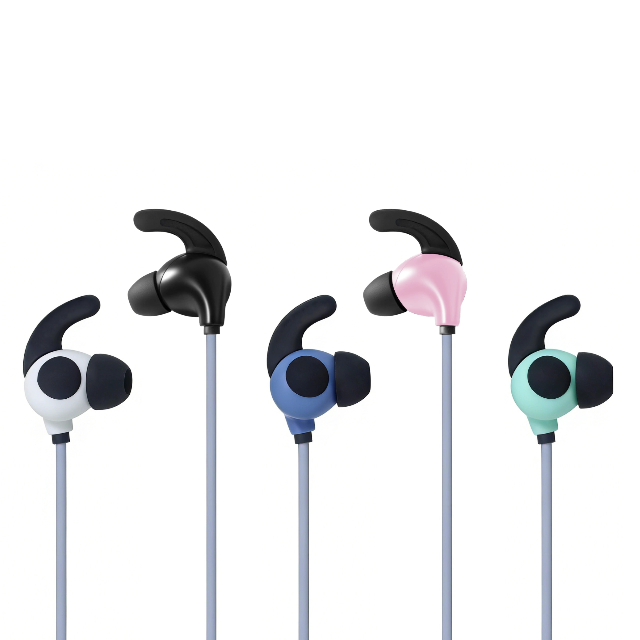
Appearance: Electrode body color, cable color, markings and product identification can be adapted to the project.
OEM/ODM presentation: Logo, labeling, accessory configuration and packaging can be developed according to private-label requirements.
Controller and Ear Electrode Should Be Verified as One Interface System
A passive ear electrode cable does not define the stimulation parameters of the completed device. Electrical output, waveform, polarity and operating logic are generated by the host controller and must be evaluated together with the electrode interface.
Heymed Medical can review the controller pinout, cable definition and ear-contact structure as one development system. Customers can provide PCB information, connector drawings, electrical requirements or existing prototypes before sampling.
This approach helps reduce the risk of selecting a mechanically matching connector with an incorrect electrical configuration and provides a clearer path from engineering sample to production-ready assembly.
Reusable Electrode Design and Material Considerations
The conductive silicone ear-contact structure is intended for reusable product integration. Repeated handling, cable flexing, cleaning method and contact condition should be considered when defining the completed product requirements.
Patient-contact materials and cleaning instructions should be evaluated according to the intended device, destination market and applicable product requirements. Final compatibility and performance should be verified by the finished-device manufacturer under the intended operating conditions.
From Interface Review to OEM/ODM Production
Development can begin from a device model, connector drawing, electrical pinout, electrode sample or complete product requirement. Heymed Medical can review the mechanical and electrical interfaces before preparing engineering samples.
During prototype development, connector mating, polarity, pin-to-contact continuity, electrode geometry, cable dimensions and strain relief can be checked against the approved project definition.
Once the configuration is confirmed, cable molding, electrode assembly, inspection, labeling and packaging can move into repeatable production. Projects requiring additional connector or cable development can also be supported through our Custom Medical Cable Assemblies engineering and manufacturing capability.

 Search