Explore product updates, engineering guides, application insights, and exhibition news from Heymed Medical, covering medical cable assemblies, EEG electrodes, neurostimulation accessories, and OEM/ODM development.
An ear clip electrode can be a useful interface in an EEG or related biosignal acquisition system, but the clip shape alone does not tell an engineer what the electrode does. Depending on the acquisition circuit, the connection may be assigned to a reference, ground, bias or another defined channel.
For OEM device teams, the practical task is to match the intended ear-contact location with the channel definition, contact material, connector, wiring and cable assembly. A visual match to an existing accessory is not enough to confirm system compatibility.
EEG product teams sometimes use “reference electrode” as a shorthand for any ear clip. That wording is only accurate when the host-system manual or circuit definition actually assigns the ear electrode to a reference function. Another system may place the same-looking clip on ground, bias or a separate acquisition input.
Before releasing a product specification, request the acquisition-module model, channel table or approved connection diagram. Where the role has not been established, describe the component neutrally as an “EEG ear clip electrode” rather than claiming a fixed reference function.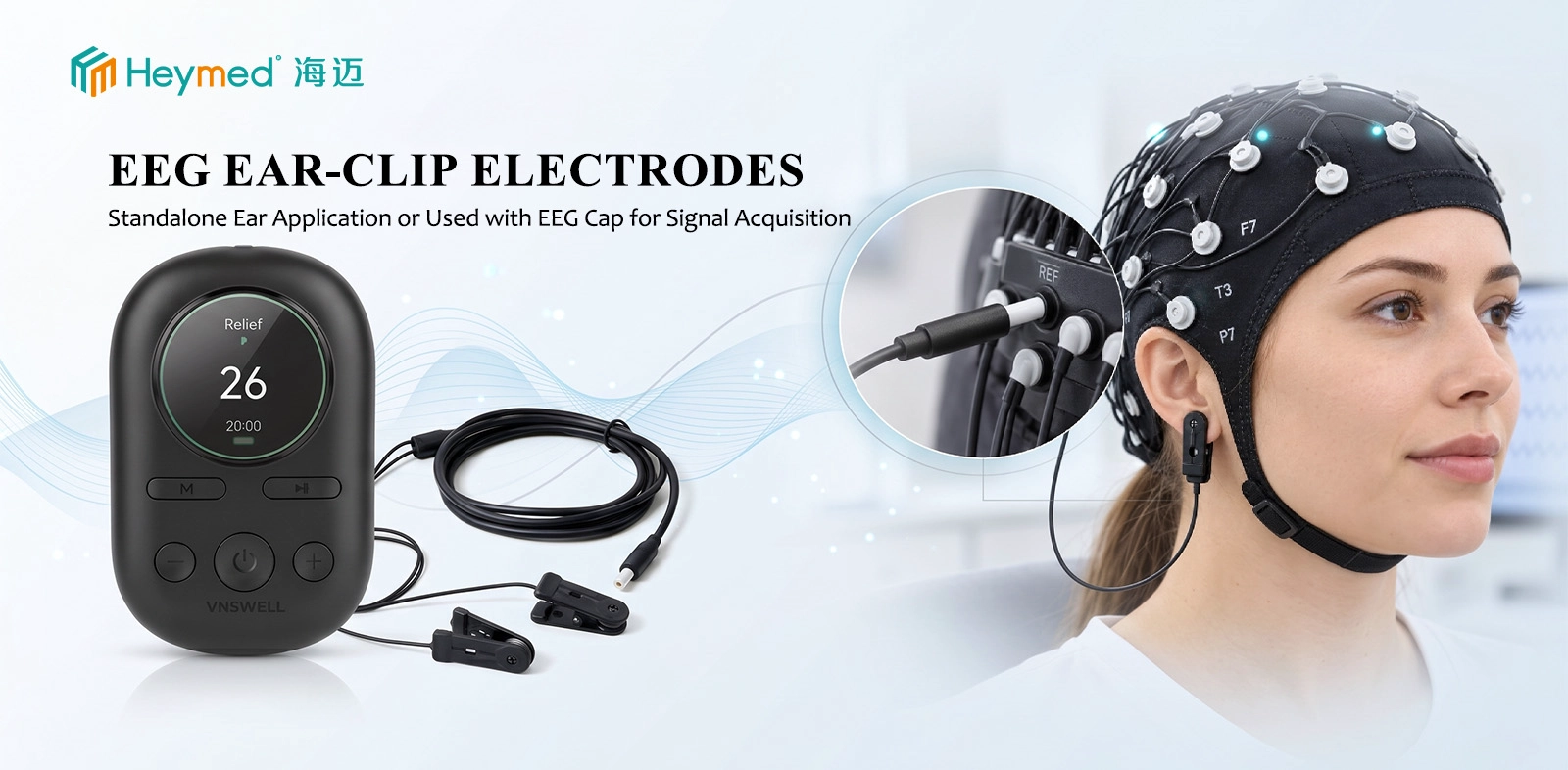
The contact may be on the earlobe or another validated external-ear position. Its dimensions, clip opening and cable exit should follow the intended location and the actual mechanical constraints. Contact shape does not define electrical channel assignment.
On the device side, matching connector pitch is only the beginning. For example, Heymed Medical’s 2.54mm Dupont to Ag/AgCl Ear Clip Electrode Cable provides a reference for configurable connector gender, wiring and lead length; the customer’s terminal map still governs the finished assembly.
Ask for a mating connector specification, pin-by-pin wiring map and an approved sample where possible. These inputs help distinguish a mechanically fitting cable from an electrically verified cable.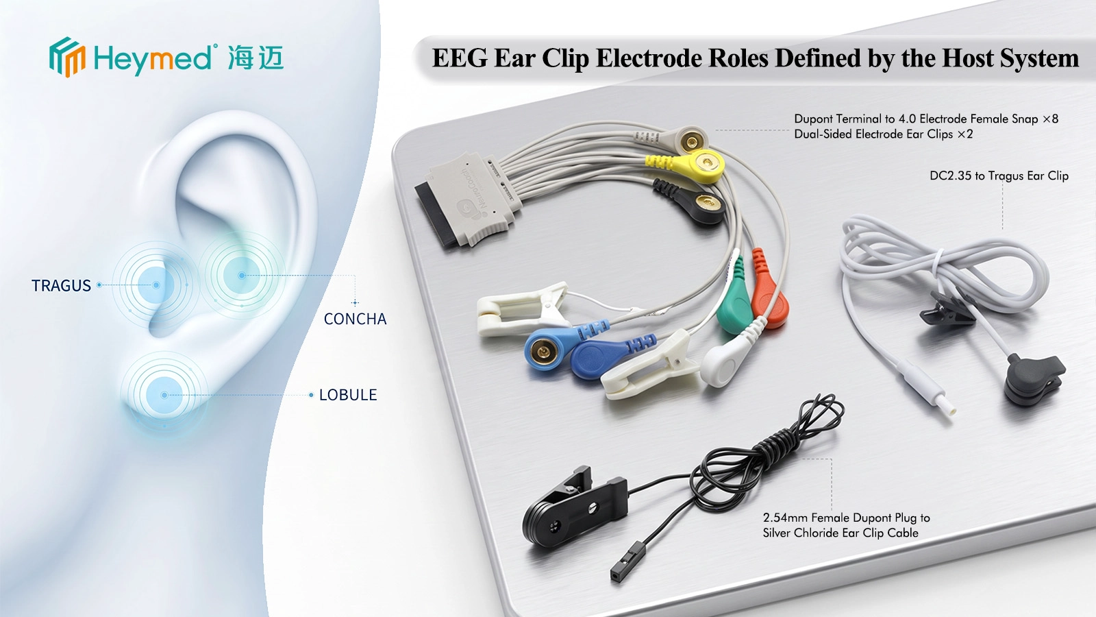
Overall length, conductor count, shielding, jacket flexibility, branch length and strain relief should be documented as part of the system interface. A longer cable or additional shielding is not automatically an improvement: noise behavior depends on the complete front-end design, cable routing and operating environment.
For an OEM configuration, the drawing should identify conductor-to-terminal mapping and any left/right or channel labels. When reviewing broader EEG & EMG Electrodes & Cables, compare the device-side electrical requirements before selecting an assembly merely because its connector looks familiar.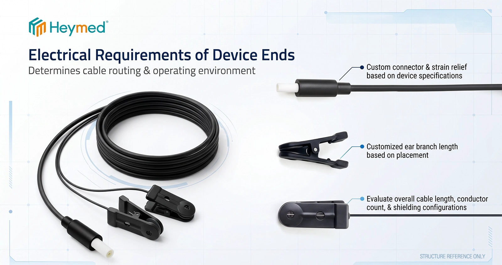
An external ear clip uses an opening jaw or spring mechanism to reach a defined surface contact. An in-ear or ear-canal electrode uses a different retention structure and may position contacts inside or around the canal. The two approaches have different geometry, user-interface and cable-routing constraints.
A similar distinction applies to acquisition and stimulation. EEG equipment measures signals; a CES or tVNS accessory forms part of a stimulation system. They should not be described as interchangeable without device-specific engineering validation.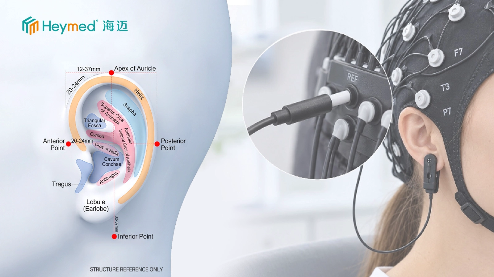
Sample approval should be based on the host-device definition and agreed acceptance criteria, not only on a product photograph. For a typical project, the joint review covers contact placement, clip operation, actual connector fit, pin-to-pin continuity, cable routing and channel identification.
If the acquisition system specifies contact impedance, signal checks or preparation conditions, those requirements should be agreed as part of the device-level verification plan. No universal contact-resistance or impedance target should be inferred from the material name alone.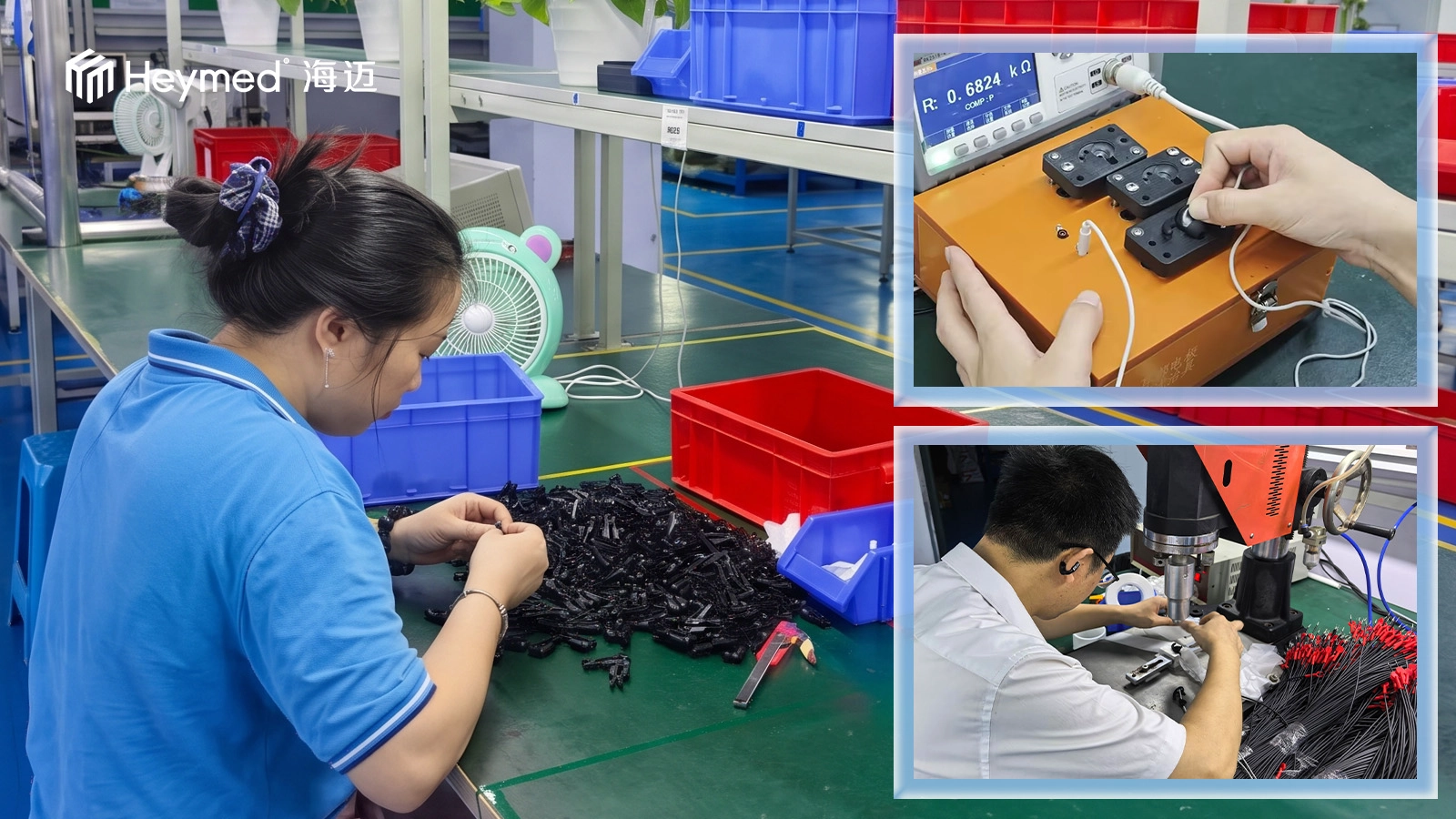
A useful first review package contains the device or acquisition-module type, intended electrode function, target contact position, clip reference or photo, connector drawing, channel/pinout map, cable length and expected prototype quantity. A working reference sample is helpful but not always required to begin discussion.
If part of the interface is still undecided, a medical OEM/ODM project review can identify which points require engineering confirmation before the supplier quotes a repeatable production configuration.
No. The role can be reference, ground, bias or another channel defined by the acquisition system. Confirm the connection diagram before using a role-specific name.
No. Material and appearance do not establish connector, channel or mechanical compatibility.
Not necessarily. Shielding should be specified by the acquisition architecture and assessed in the complete system.
Yes. A supplied pin map, connector drawing or working sample can form the basis of an OEM engineering review.
Send the acquisition-device model, connector drawing and pinout, together with your preferred ear-contact position. Heymed Medical can review the contact, cable and device interface as one project.
Send Your Drawing or SampleWork with Heymed Medical on OEM/ODM development and controlled manufacturing for tVNS and taVNS products, EEG electrodes, medical lead wires, custom cable assemblies, and medical docking and charging products—from engineering samples and validation to volume production.
Tell our engineering team about your product application, device interface, performance targets, compliance needs, and expected quantity. We will review your information and contact you to discuss technical feasibility, customization options, and recommended next steps.
Tip: A drawing, device interface photo, pinout diagram, or reference sample can help our engineering team evaluate your project more accurately and efficiently.
 Search