 Search











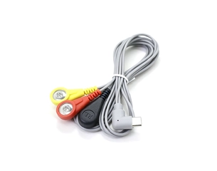
USB-C 90° Right Angle to 3-Lead 4.0mm ECG Female Snap Electrode Cable
1m Grey 3-Lead Electrode Cable with Red, Yellow and Black 4.0mm Female Snap Connectors | Custom USB-C Pinout & OEM/ODM Development


Explore tVNS and taVNS devices and electrodes, EEG electrodes and caps, ECG/EMG lead wires, therapy accessories, custom medical cable assemblies, and medical charging docks.
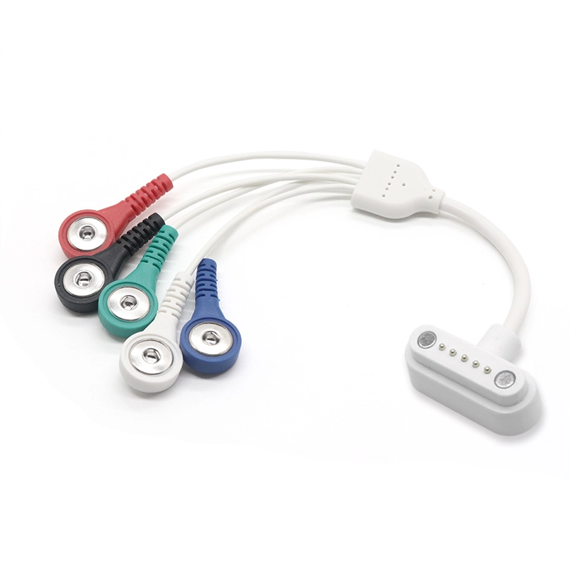
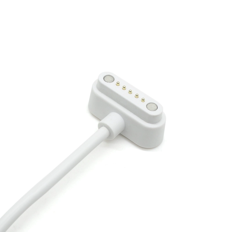
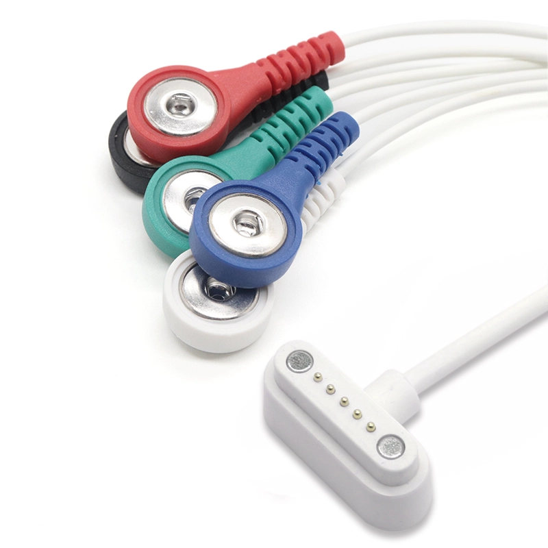
Compact 5-lead electrode cable with a 5-pin spring-loaded device interface for compatible ECG, EMG and biosignal equipment | Custom pinout and OEM/ODM available
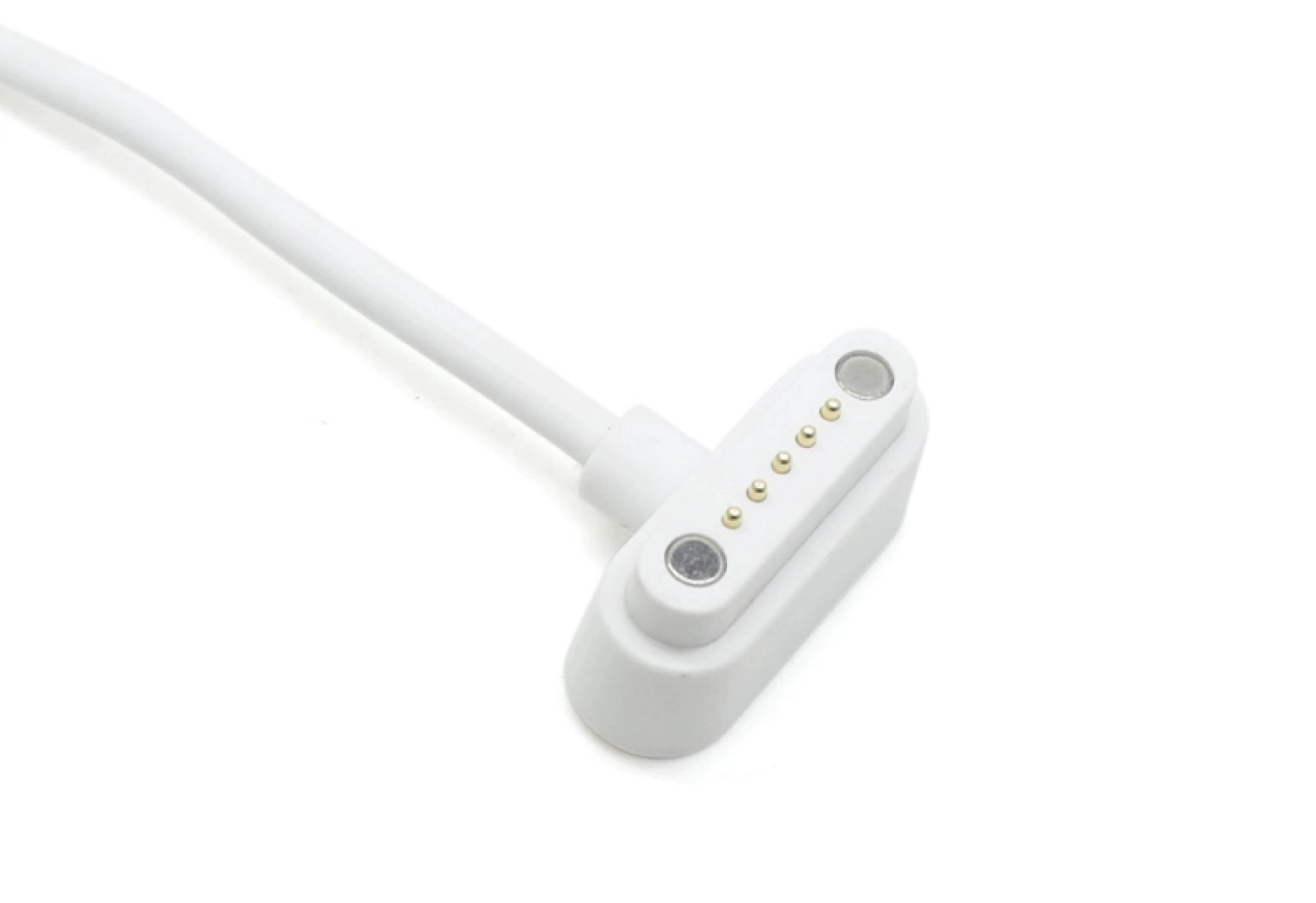
The Heymed Medical 5-Pin Spring-Loaded Contact to 5-Lead ECG/EMG Electrode Cable is designed for compatible ECG, EMG and biosignal acquisition equipment requiring a compact multi-contact device interface and multiple electrode connections.
The cable combines a 5-pin spring-loaded contact connector with a five-lead electrode cable structure, allowing the electrode-side interface to be configured according to the target device and electrode system.
Heymed Medical supports customization of the pin assignment, cable length, lead configuration, electrode connector, cable structure, overmold, labeling and packaging for OEM/ODM medical device projects.
Solutions & Applications
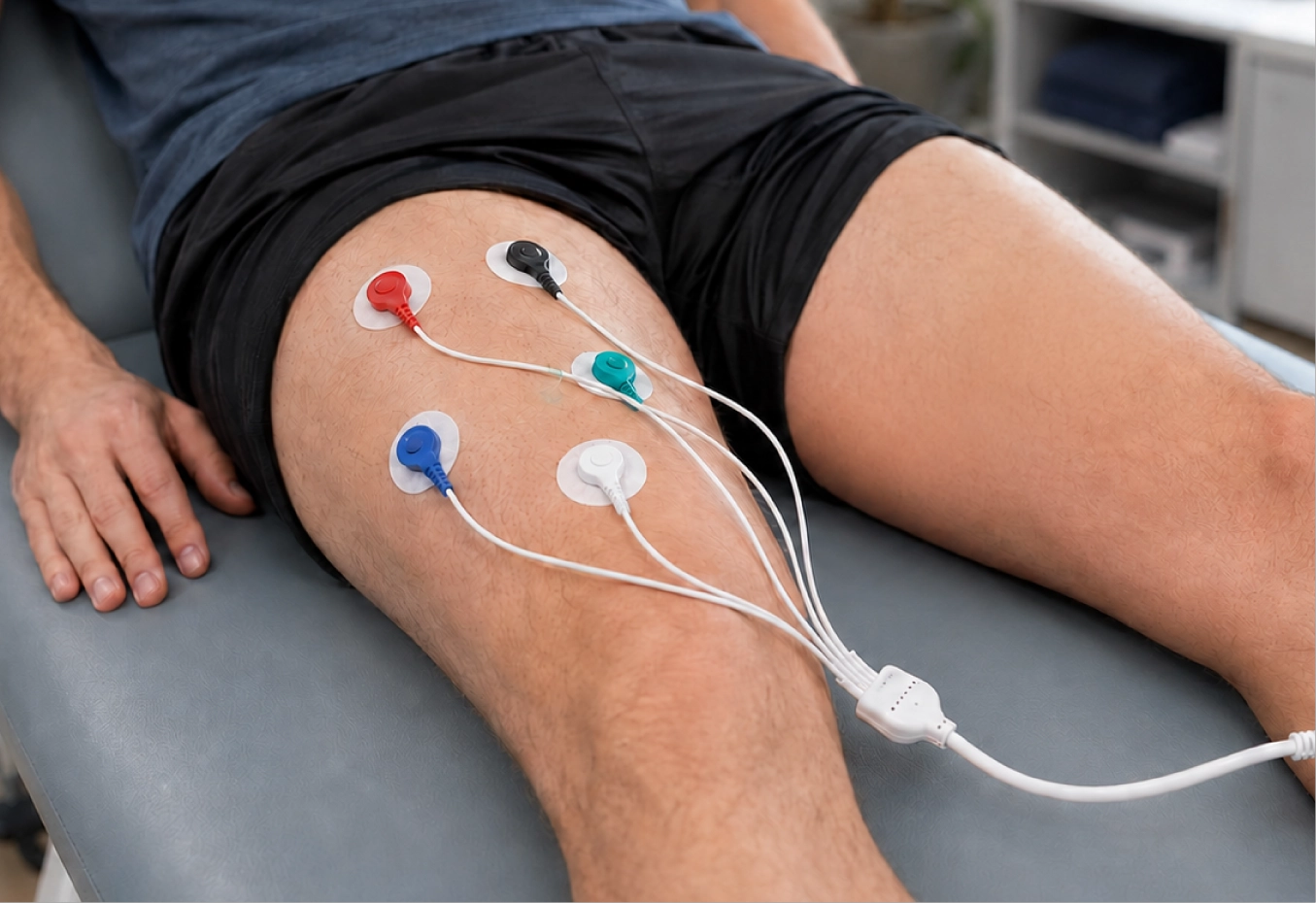
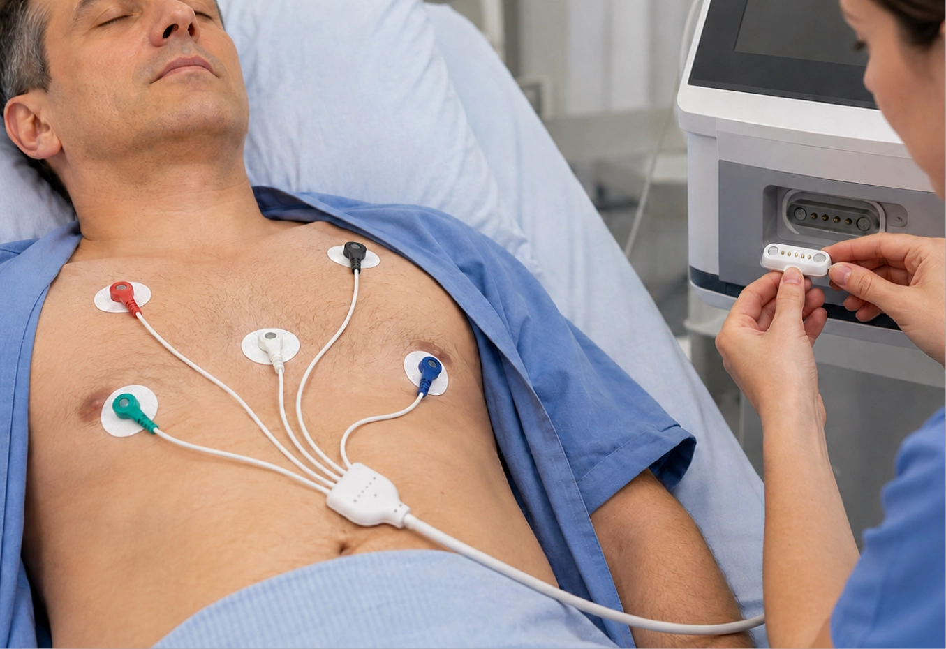
The 5-Lead ECG / EMG Electrode Cable provides configurable connectivity between compatible ECG equipment, EMG systems and biosignal acquisition devices. The compact 5-pin spring-loaded interface is suitable for equipment requiring a multi-contact connection within a limited device space.
For OEM/ODM projects, spring-contact layout, pin assignment, electrode-side connector, cable length, lead configuration, cable structure and overmold design can be developed according to the finished-device architecture. The cable can also be integrated into broader ECG Lead Wires, EMG Cables, Biosignal Cables or Custom Medical Cable Assemblies.
Heymed Medical supports device interface review, pinout confirmation, connector integration, cable structure design, prototype development, continuity testing and volume manufacturing. Customers can provide device drawings, contact layouts, pin definitions, existing cable samples or interface dimensions for engineering evaluation.
Medical-grade auricular stimulation cable specifications for healthcare and neuromodulation therapy applications.
This custom 5-lead electrode cable combines a compact 5-pin spring-loaded device connector with five individual 4.0mm female snap leads. It provides an organized connection between compatible ECG, EMG, patient-monitoring and biosignal acquisition equipment and multiple snap-type electrodes.
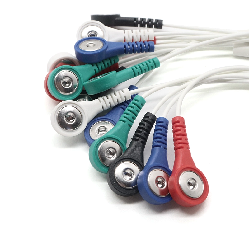
The flexible medical-grey TPU cable supports repeated handling in portable and integrated equipment, while individual lead colors and markings can be configured to simplify channel identification. Device-side pin assignment, lead length, branch structure and electrode snap configuration can be developed according to the actual equipment interface.
Multi-channel biosignal equipment often requires several electrode connections while keeping the equipment-side connector compact. This cable brings five individual electrode leads into a single 5-contact device interface, helping simplify cable routing around portable monitoring and physiological signal acquisition equipment.
Each branch terminates in a 4.0mm female snap connector for mating with a compatible male electrode stud. Lead colors, labels and channel markings can be selected according to the customer's approved electrical definition so that each electrode connection can be identified clearly during assembly and use.
A five-lead cable does not by itself define a standardized ECG or EMG channel arrangement. Electrode function, signal assignment, reference connection and channel sequence depend on the target device and should be confirmed before prototype production.
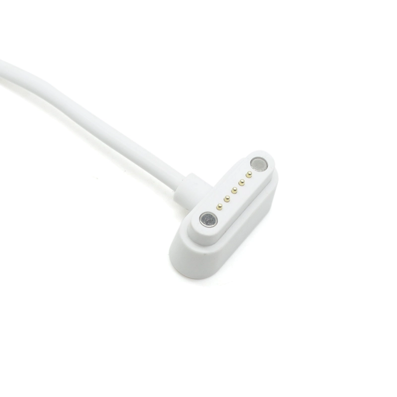
The equipment-side connector uses spring-loaded electrical contacts in a compact housing. This type of interface is useful when the device requires a detachable cable connection but has limited enclosure space for a larger circular or rectangular connector.
Spring contacts provide controlled contact travel when the cable mates with the corresponding device interface. The connector housing, alignment features, contact spacing and cable exit direction should be designed together with the equipment enclosure to achieve reliable mechanical engagement.
Similar-looking spring-contact connectors are not automatically interchangeable. Contact spacing, orientation, mechanical dimensions and electrical pin assignment must all be matched to the intended device.
Device connector: contact quantity, pitch, orientation, housing dimensions and mating structure.
Pinout: electrical mapping between each device-side contact and the corresponding electrode lead.
Electrode interface: 4.0mm female snap geometry and compatibility with the intended male electrode stud.
Lead configuration: lead quantity, individual branch length, color identification, labels and breakout position.
Cable construction: total length, TPU jacket, conductor structure, shielding, strain relief and overmold design according to the finished equipment.
Mechanical connector fit alone is not sufficient for a medical lead-wire assembly. Each of the five device-side contacts must be mapped to the correct electrode lead according to the electrical architecture of the target equipment.
Heymed Medical can review PCB pin definitions, connector drawings, wiring diagrams, channel tables, device interface photographs or existing cable samples before prototype development. This allows the complete lead-wire mapping to be defined according to the approved equipment specification.
This engineering review is especially important for replacement-cable development and new equipment projects, where two connectors with similar dimensions may use different channel assignments.
The five-lead structure can be adapted to different equipment layouts through changes in cable length, breakout position and individual branch dimensions. This allows the lead-wire assembly to be arranged around the electrode positions and physical dimensions of the finished device rather than forcing the equipment to use a fixed cable geometry.
Depending on the project, channel identification can be created using different overmold colors, printed labels or numbered markings. Snap size and cable structure can also be reviewed where the target electrode system requires a different connection format.
For additional device-side connector structures and lead configurations, explore our ECG Cables & Lead Wires for related patient-monitoring and biosignal cable solutions.
Heymed Medical supports custom ECG, EMG and biosignal cable projects from interface review and cable-structure development through prototype sampling and volume manufacturing. Customers can provide device drawings, connector dimensions, pinout definitions, electrode specifications or an existing reference cable for engineering evaluation.
During sample development, connector mating, electrical continuity, channel mapping, snap engagement, lead dimensions and cable workmanship can be checked against the approved project requirements.
Once the electrical and mechanical configuration is confirmed, the cable can move into repeatable assembly, inspection and production according to the agreed specification.
Different ECG and biosignal devices may use different channel counts and equipment-side interfaces while retaining similar snap-style electrode connections.
4-Pin Spring-Loaded Contact to 3-Lead 4.0mm ECG Female Snap Cable →
A compact three-lead alternative for compatible ECG and patient-monitoring equipment requiring fewer electrode channels.
USB-C 90° Right Angle to 3-Lead 4.0mm ECG Female Snap Electrode Cable →
An alternative three-lead architecture using a right-angle Type-C device interface for compact medical and biosignal equipment.
We provide OEM and ODM medical cable assembly services for neuromodulation therapy device manufacturers and healthcare brands worldwide.
1m Grey 3-Lead Electrode Cable with Red, Yellow and Black 4.0mm Female Snap Connectors | Custom USB-C Pinout & OEM/ODM Development
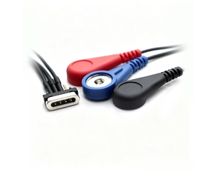
Compact 1-to-3 electrode lead cable with a 4-pin spring-loaded device connector and three 4.0mm female snaps for compatible ECG and patient-monitoring equipment.
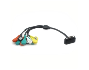
10-lead ECG electrode cable with a magnetic spring-loaded device interface and ten 4.0mm female snap connectors | Custom pinout, cable length and OEM/ODM available
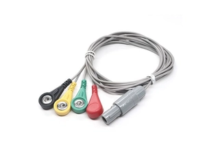
Shielded 3-lead ECG cable with a 4-pin push-pull device connector and three 4.0mm female snap interfaces for compatible ECG and patient-monitoring equipment | Custom pinout & OEM/ODM available
Resolve your concerns in advance — stress-free communication, efficient coordination
It is a multi-lead medical cable assembly that connects a compatible device through a 5-pin spring-loaded contact interface and provides five separate electrode leads for ECG, EMG or biosignal acquisition applications.
It can be developed for compatible ECG equipment, EMG systems and biosignal acquisition devices. Final compatibility depends on the device interface, contact layout, pin assignment and electrical requirements.
The device side uses a compact 5-pin spring-loaded contact connector. The contact layout and mechanical interface should be matched to the target equipment.
Yes. The five electrode leads can be configured with project-specific electrode connectors according to the target electrode system and equipment requirements.
Yes. Contact layout, pin assignment, cable length, lead configuration and electrode-side interfaces can be developed according to the customer's device drawings and approved design.
Yes. Customers can provide device drawings, contact-pad layouts, pin definitions, interface dimensions, existing cable samples or reference photos for engineering evaluation and prototype development.
Yes. Heymed Medical supports device-interface review, pinout confirmation, connector integration, cable structure development, continuity testing, customization and volume manufacturing for ECG, EMG and biosignal cable projects.

Heymed Medical develops and manufactures OEM/ODM medical and wellness products for patient monitoring, EEG and brain monitoring, tVNS/taVNS neuromodulation, physiotherapy and rehabilitation, diagnostic equipment, and medical docking and charging applications.
Our portfolio includes tVNS/taVNS devices, auricular and ear clip electrodes, dry and wet EEG electrodes, EEG caps, ECG/EMG lead wires and electrodes, TENS/EMS lead wires and accessories, custom medical cable assemblies, Pogo Pin connectors, and charging docks.
Work with Heymed Medical on OEM/ODM development and controlled manufacturing for tVNS and taVNS products, EEG electrodes, medical lead wires, custom cable assemblies, and medical docking and charging products—from engineering samples and validation to volume production.
Tell our engineering team about your product application, device interface, performance targets, compliance needs, and expected quantity. We will review your information and contact you to discuss technical feasibility, customization options, and recommended next steps.
Tip: A drawing, device interface photo, pinout diagram, or reference sample can help our engineering team evaluate your project more accurately and efficiently.