 Search










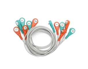
Multi-Lead EEG / ECG / EMG Monitoring Electrode Cable
Reusable shielded biosignal lead wire with Dupont, 4.0mm female snap and ear-clip electrode interfaces for compatible EEG, ECG, EMG and sleep monitoring equipment


Explore tVNS and taVNS devices and electrodes, EEG electrodes and caps, ECG/EMG lead wires, therapy accessories, custom medical cable assemblies, and medical charging docks.
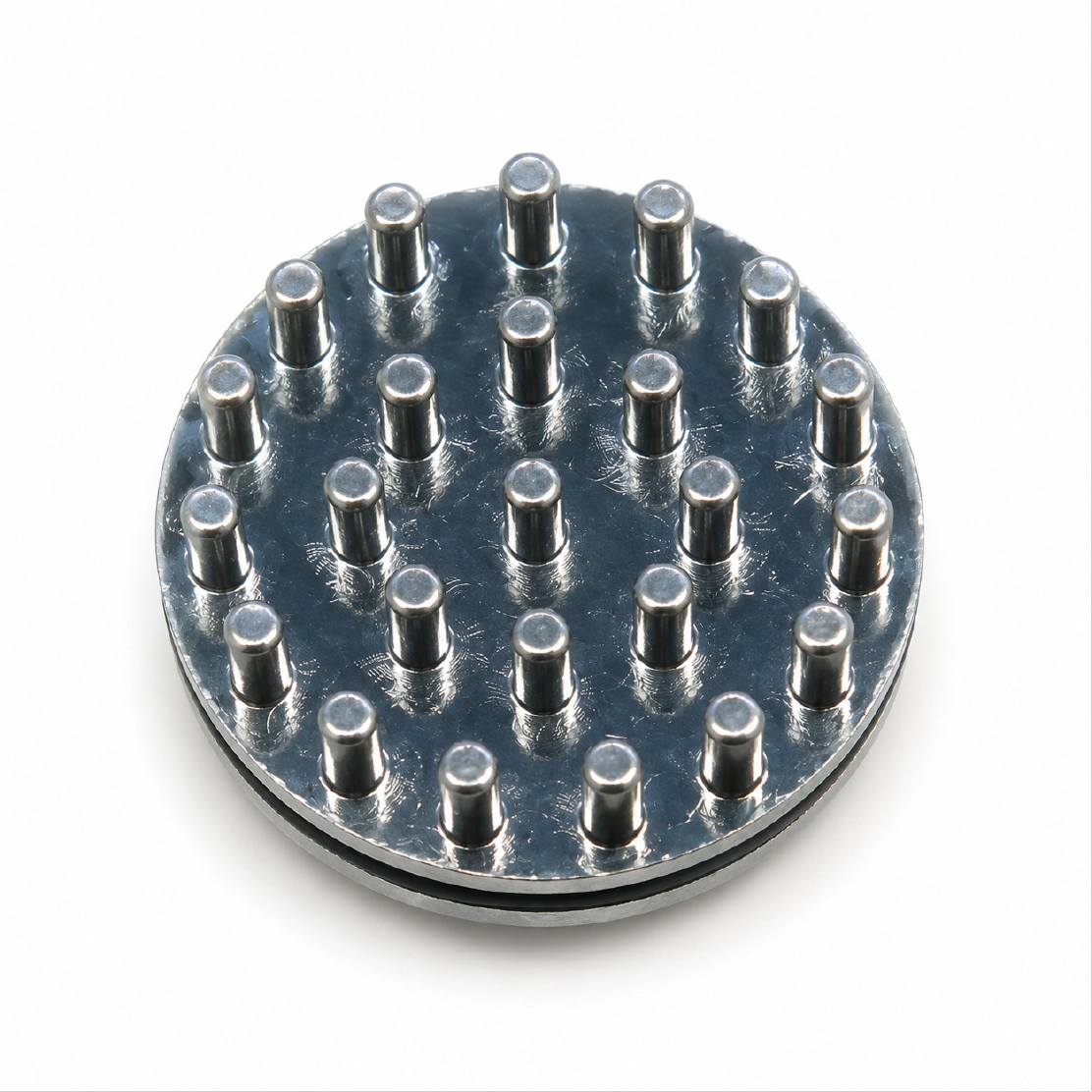
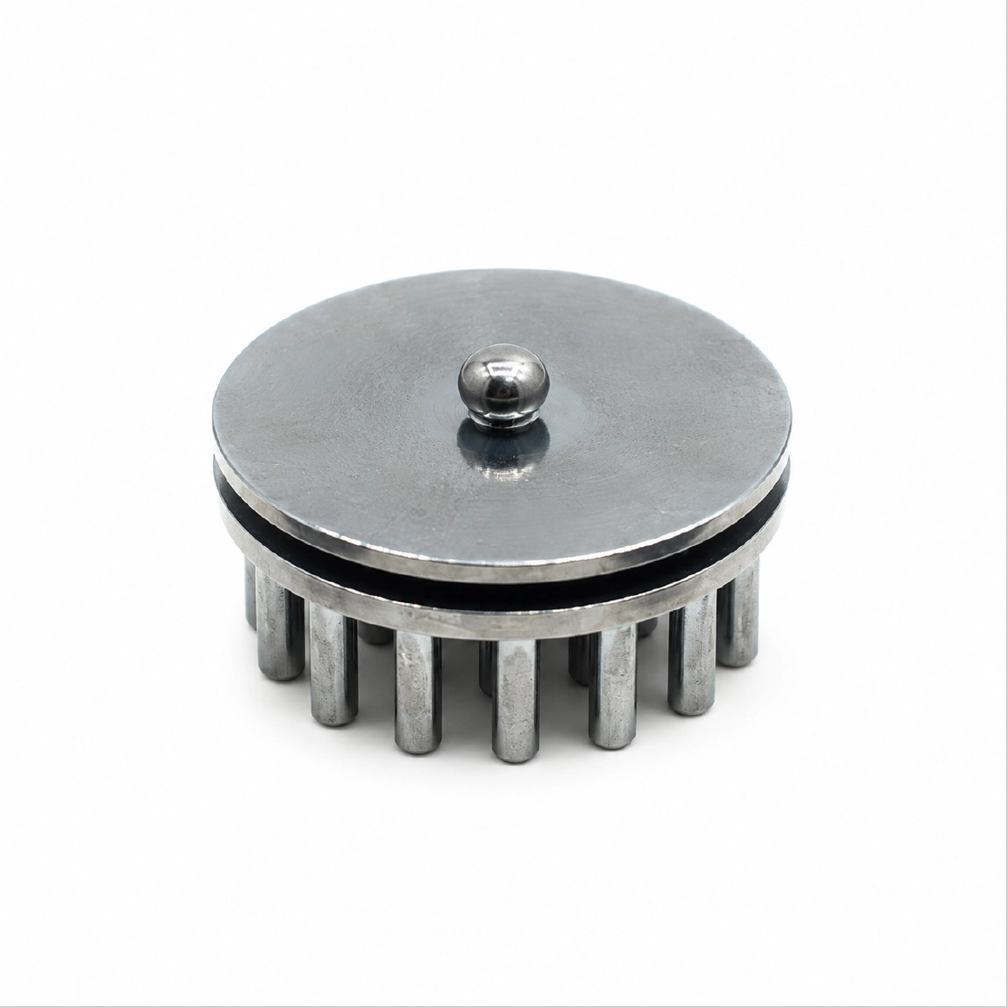
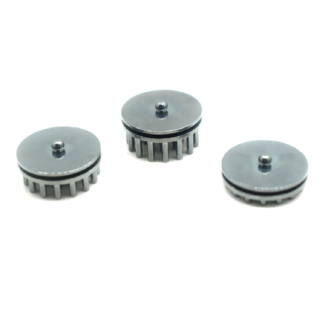
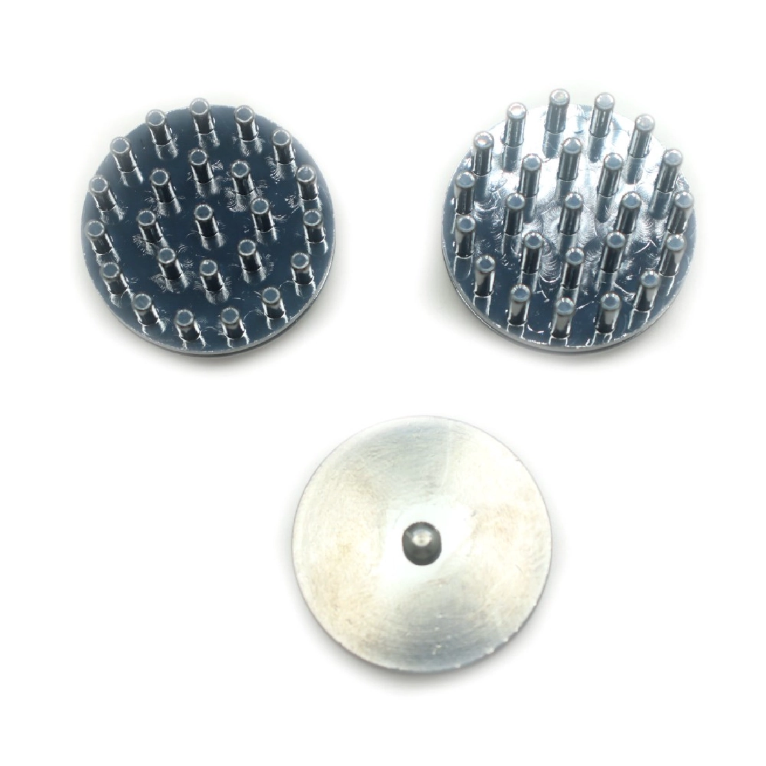
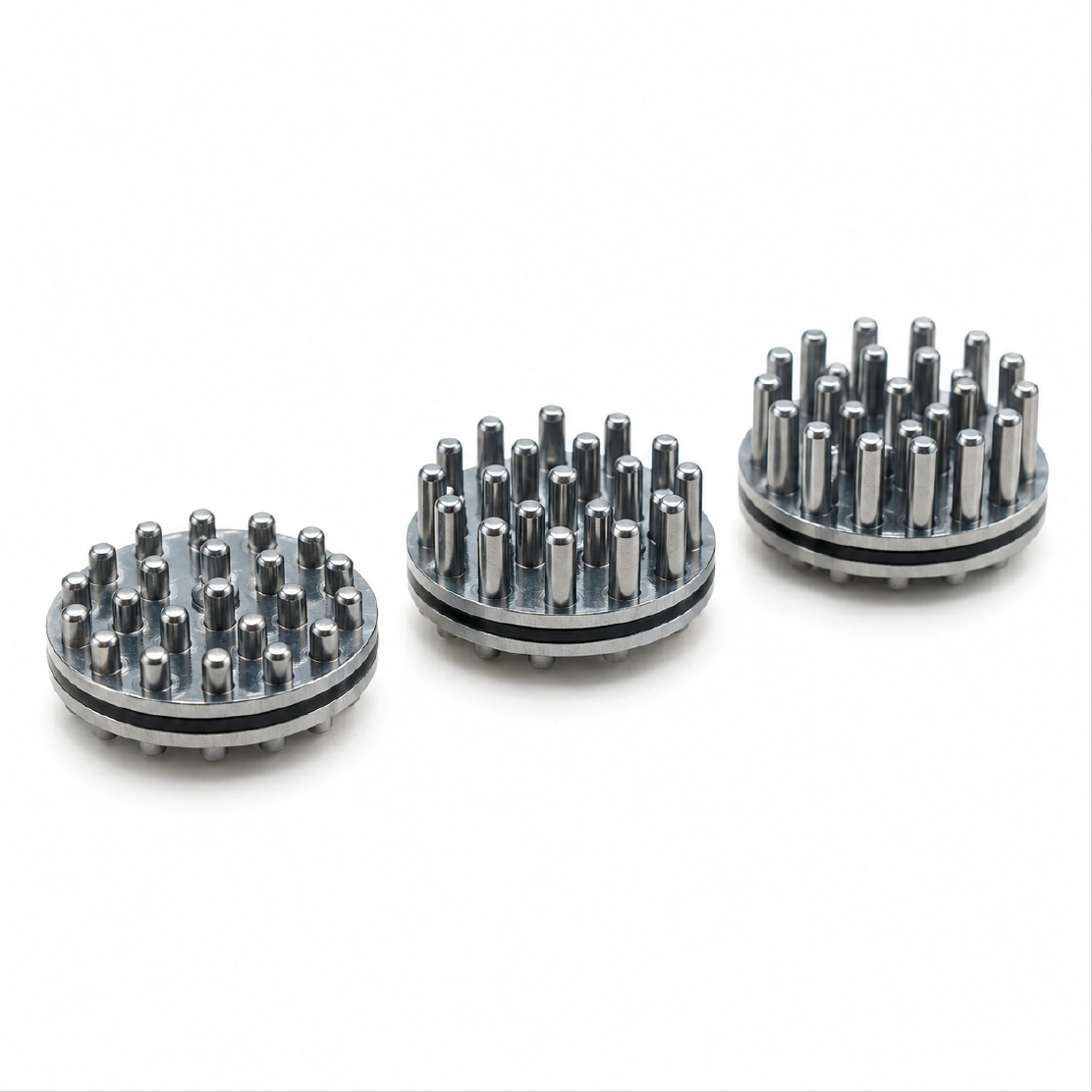
China manufacturer of 24-pin comb dry EEG electrodes for equipment OEMs, with a 3.9mm male snap and customization of pin layout, surface finish and matching lead assemblies
Heymed Medical manufactures Ag/AgCl comb dry EEG electrodes in Dongguan, China, for EEG equipment brands and OEM system developers. This version combines a circular 24-pin contact array with a 3.9mm male snap for a detachable lead connection. The pins describe the contact structure, not 24 independent recording channels.
Buyers can request the reference configuration or discuss custom pin layouts, surface finishes and matching lead assemblies. Share the electrode drawing, holder dimensions and mating connector sample so Heymed Medical can review fit, prepare project samples and quote the approved configuration for production supply.
Solutions & Applications
For EEG headset manufacturers and biosignal equipment integrators, Heymed Medical supplies comb dry electrode components with a 24-pin array and a 3.9mm male snap. Review the electrode with the intended holder, lead connection and acquisition system to define a configuration suitable for your equipment.
OEM/ODM development can cover pin layout, surface finish and matching cable assemblies. For bulk procurement, submit the approved configuration, order quantity and required delivery date for quotation. Sample fit and acquisition performance should be evaluated before confirming the production specification.
Medical-grade auricular stimulation cable specifications for healthcare and neuromodulation therapy applications.
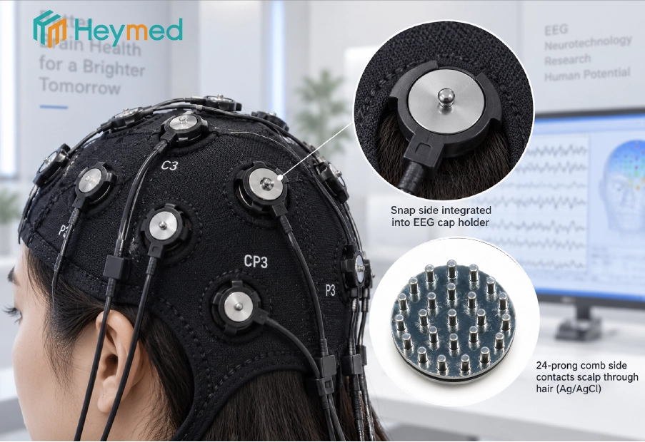
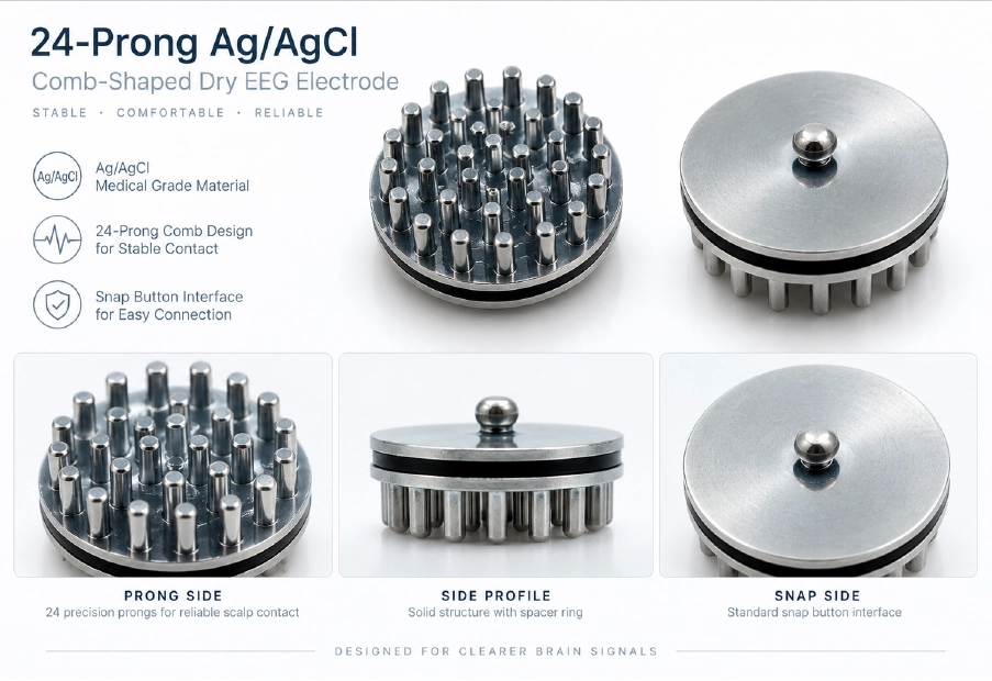
Designed for scalp biosignal acquisition, this comb-shaped dry electrode has 24 contact prongs arranged within a single circular electrode head. The prongs form a distributed contact surface that can reach through hair when the electrode is positioned and held correctly. A 3.9mm snap-style connection at the base allows the electrode to be paired with a matching holder or lead-wire interface.
The 24 prongs belong to one electrode contact assembly; they should not be confused with 24 independent EEG recording channels. This distinction matters when selecting sensors for EEG caps, research headsets and custom electrophysiology equipment. Heymed Medical can review the Ag/AgCl contact specification, prong geometry and snap-side integration against the intended acquisition system.
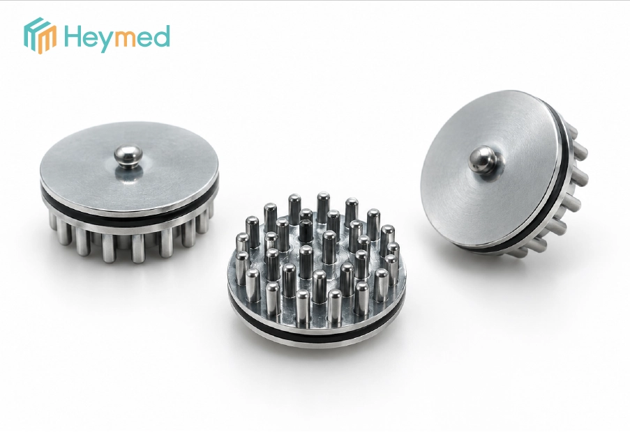
Comb-shaped electrode head and contact arrangement. Prong spacing, overall dimensions and contact finish are defined by the approved sample.
Hair can prevent a flat electrode surface from making consistent contact with the scalp. A comb-shaped head uses multiple small prongs to distribute the contact area while allowing the electrode to sit between hair strands. This makes the geometry worth considering for dry-contact EEG sensor designs where repeated positioning and manageable setup are important.
Actual recording quality still depends on hair density, electrode pressure, head movement, contact condition, amplifier characteristics and the complete measurement circuit. The comb structure alone does not guarantee a particular impedance, signal-to-noise ratio or gel-free recording result. These factors should be evaluated on the intended headset or EEG cap.
The base uses a nominal 3.9mm snap interface so the electrode can be detached from a compatible holder or lead wire. During development, the mating snap geometry, retention force, mounting depth and available clearance need to be checked with the actual cap or headset components.
The 24 prongs describe the contact structure on the skin-facing side. They do not define the number of electrical channels at the snap. In a complete EEG setup, the number of measurement channels comes from the electrode locations, wiring and amplifier design—not from the count of prongs on one electrode head.
For multi-position scalp setups, this sensor concept can be evaluated alongside a 32-Channel EEG Electrode Cap with 10–20 Electrode Positioning, subject to confirmation of holder dimensions and the actual electrical interface.
Reference views of the electrode body and snap connection. Final mechanical fit must be checked using a mating sample.
Silver/silver chloride (Ag/AgCl) is used in electrophysiological electrode interfaces because its electrochemical behavior can be useful for recording small biological potentials. On a dry comb electrode, the material specification must be considered together with the prong shape, contact pressure, surface condition and repeated-use requirements.
Heymed Medical can discuss electrode material and surface-finish requirements during engineering review. Whether a particular contact process, cleaning method or reuse cycle is suitable must be established through product-level testing. No fixed impedance value or biocompatibility result should be assumed without the relevant test data.
Our EEG & EMG Electrodes & Cables range covers other electrode formats and biosignal connection approaches when a comb contact is not the best fit.
Electrode type: Single comb-shaped dry-contact electrode.
Contact structure: Circular array of 24 prongs.
Contact material: Ag/AgCl specification subject to the approved material and surface-finish drawing.
Connection: Nominal 3.9mm snap-style electrode interface; mating geometry to be verified.
Mechanical design: Prong height, spacing, tip profile, base dimensions and retention requirements reviewed for the target holder.
System integration: EEG cap or headset mounting, matching lead wire, amplifier input and reference/ground arrangement.
OEM/ODM options: Contact layout, electrode housing, materials, packaging and compatible cable or holder integration, subject to engineering review.
A useful evaluation begins with the electrode position and mounting method. Will it sit in a fabric cap holder, a rigid headset module or another fixture? How much clearance is available around the 3.9mm snap? Can the prongs reach the intended scalp-contact area without excessive pressure? These questions affect both mechanical design and recording repeatability.
For sample assessment, customers can provide a cap holder or headset drawing, mating snap sample, electrode dimensions, expected wearing conditions and acquisition-device requirements. The resulting sample can then be checked for fit, contact consistency, handling and cleaning compatibility under the actual project conditions.
Rather than selecting an EEG dry electrode by a nominal connector size alone, Heymed Medical can work from a reference electrode, contact-surface drawing or headset design to define the complete mechanical interface. The agreed sample and inspection requirements then guide subsequent assembly and production.
For a project involving custom electrode holders, connectors or matching lead wires, our Medical Cable OEM/ODM Customization service can support coordinated design review and prototype preparation.
Please share the desired electrode geometry, snap mating details, installation method, application environment and expected volume when requesting a quotation. Any clinical performance, patient-contact safety or regulatory claims for the finished product must be supported by the applicable verification and approval process.
We provide OEM and ODM medical cable assembly services for neuromodulation therapy device manufacturers and healthcare brands worldwide.
Reusable shielded biosignal lead wire with Dupont, 4.0mm female snap and ear-clip electrode interfaces for compatible EEG, ECG, EMG and sleep monitoring equipment
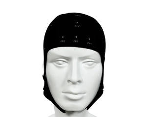
32-channel EEG electrode cap based on the International 10–20 positioning system, with configurable electrode materials, cap sizes and device interfaces for EEG acquisition projects.
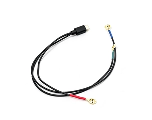
Reusable gold-plated cup electrode lead wire for EEG, ECG, EMG and PSG biosignal acquisition | Custom Type-C pinout, lead length and OEM/ODM available
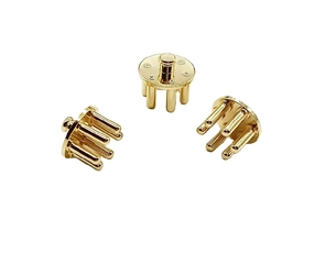
Compact multi-pin connector for EEG caps, headsets and biosignal acquisition equipment | Custom pin layout, dimensions and mounting structure available
Resolve your concerns in advance — stress-free communication, efficient coordination
Yes. Heymed Medical manufactures Ag/AgCl comb dry EEG electrodes in Dongguan, China, for equipment brands and OEM developers. The reference design has 24 contact pins and a 3.9mm male snap. Buyers can discuss the reference configuration, matching leads and project-specific customization.
Pin layout, surface finish and the matching lead assembly can be reviewed for customization. Provide the holder drawing, contact geometry requirements and mating snap sample. The 24-pin reference describes contact geometry; it does not specify 24 independent EEG channels.
Compatibility must be checked with the actual mating snap or an approved drawing. Nominal size alone does not confirm engagement, retention or electrical connection. Share the lead connector dimensions or a sample for fit review.
Contact Heymed Medical with the configuration and quantity needed for evaluation and production. Sample availability, sample charges, minimum order quantity and lead time are quoted for the specific design. Confirm the sample against the intended holder, lead and acquisition system before approving bulk production.
Provide the electrode drawing or sample, mounting dimensions, mating snap specification, surface requirements and any matching cable details. Include evaluation quantity, expected production volume and required delivery date. Heymed Medical can review the requirements and quote the agreed scope of electrode and lead assembly supply.

Heymed Medical develops and manufactures OEM/ODM medical and wellness products for patient monitoring, EEG and brain monitoring, tVNS/taVNS neuromodulation, physiotherapy and rehabilitation, diagnostic equipment, and medical docking and charging applications.
Our portfolio includes tVNS/taVNS devices, auricular and ear clip electrodes, dry and wet EEG electrodes, EEG caps, ECG/EMG lead wires and electrodes, TENS/EMS lead wires and accessories, custom medical cable assemblies, Pogo Pin connectors, and charging docks.
Work with Heymed Medical on OEM/ODM development and controlled manufacturing for tVNS and taVNS products, EEG electrodes, medical lead wires, custom cable assemblies, and medical docking and charging products—from engineering samples and validation to volume production.
Tell our engineering team about your product application, device interface, performance targets, compliance needs, and expected quantity. We will review your information and contact you to discuss technical feasibility, customization options, and recommended next steps.
Tip: A drawing, device interface photo, pinout diagram, or reference sample can help our engineering team evaluate your project more accurately and efficiently.