Explore product updates, engineering guides, application insights, and exhibition news from Heymed Medical, covering medical cable assemblies, EEG electrodes, neurostimulation accessories, and OEM/ODM development.
A medical electrode cable is the wired connection between a patient-contact electrode and a monitoring, diagnostic, stimulation or rehabilitation device. Depending on its intended use, the cable may transfer low-level bioelectrical signals from the body to medical equipment or deliver controlled electrical output from a device to an electrode.
Because these functions are different, ECG acquisition leads, EEG electrode cables, TENS lead wires and tVNS ear electrode cables should not be treated as interchangeable. Selecting the correct cable requires a clear understanding of the application, electrode interface, device connector, pinout, electrical requirements, patient-contact conditions and expected service life.
A medical electrode cable assembly normally includes several functional parts:
An electrode-side interface, such as a snap, clip, pin, cup electrode, ear electrode or custom contact structure
Conductors designed for the required signal or stimulation output
Shielding or noise-control structures where required
A cable jacket selected for flexibility, durability and cleaning conditions
Branching points, lead identifiers or channel labels
A device-side connector with a defined pinout
Strain relief and overmolded sections that protect high-stress areas
The complete connection path—from the electrode and cable to the connector and host device—should be evaluated as one system. A connector that looks physically compatible may still have a different pin assignment, channel configuration or electrical requirement.
ECG lead wires connect skin electrodes to electrocardiographs, bedside monitors, Holter systems and other cardiac monitoring equipment. Common electrode-side interfaces include snaps, clips, grabbers and pins.
Important design considerations include lead identification, connector compatibility, stable signal transmission, cable flexibility, strain relief and resistance to repeated cleaning or handling.
EEG electrode cables connect dry electrodes, wet electrodes, cup electrodes, disc electrodes or EEG caps to electroencephalography and neurodiagnostic equipment.
Because EEG systems often use multiple channels and low-level signals, cable routing, shielding, channel identification, connector pinout and resistance to movement-related interference are important design factors.
Surface EMG cables transfer muscle-related electrical signals from skin electrodes to electromyography, rehabilitation or physiological measurement equipment.
Selection should consider the electrode connector, number of channels, cable length, device interface, shielding structure and expected movement during use.
TENS, EMS and physiotherapy lead wires deliver electrical output from a stimulation or rehabilitation device to compatible electrodes. Common interfaces may include pins, snaps and device-specific connectors.
These cables must be matched to the device’s output characteristics, connector configuration, polarity, channel arrangement and intended electrode system. A therapy lead wire should not be substituted for a passive signal-acquisition cable.
tVNS and taVNS cables connect a stimulation controller to an auricular electrode or ear-contact accessory. Development may involve customized ear-electrode geometry, left or right wearing configurations, channel and polarity mapping, flexible lead-wire structures and device-specific connectors.
The cable and ear-contact assembly should be evaluated for mechanical stability, repeated bending, wearing comfort and reliable electrical connection without making unsupported therapeutic claims.
Patient-monitoring cable assemblies may use a trunk cable and detachable lead set to organize multiple electrode connections. Connector keying, channel identification, cable management and compatibility with the specified monitoring system are important.
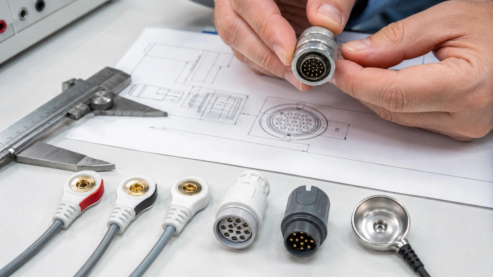
First determine whether the cable will acquire a physiological signal, deliver stimulation output, provide power or data, or perform more than one function.
The required conductor structure, shielding, insulation, connector and test plan depend on this basic definition.
Specify whether the product uses dry electrodes, wet electrodes, disposable adhesive electrodes, reusable electrodes, cup electrodes, ear electrodes or another custom contact structure.
The location, nature, frequency and duration of patient contact should also be documented. Patient-contacting materials may require appropriate biocompatibility information based on the final device and its intended use.
Connector appearance alone is not enough to confirm compatibility. The following information should be checked:
Connector manufacturer or exact model
Mechanical dimensions and keying
Pin assignment and channel mapping
Polarity requirements
Voltage and current requirements
Mating and insertion-cycle expectations
Protection against incorrect connection
Whenever possible, provide connector drawings, device interface photos, existing samples or a confirmed pinout diagram.
For ECG, EEG and EMG applications, conductor arrangement, shielding, grounding strategy, cable movement and connector design can influence system-level signal quality.
Depending on the application, the cable may use twisted conductors, individual shielding, overall shielding or other noise-control structures. The selected design should be validated with the target device rather than judged from the cable specification alone.
Medical electrode cables may be repeatedly bent, pulled, connected, disconnected, stored and cleaned. Important mechanical requirements may include:
Cable flexibility and minimum bending radius
Tensile strength and strain relief
Connector retention
Repeated flexing and torsion
Resistance to cleaning agents
Reusable or single-use configuration
Storage and transportation conditions
Before customization begins, confirm the required drawings, material records, inspection criteria, labeling, packaging, traceability and regulatory documentation.
Terms such as “medical grade,” “biocompatible” or “certified” should only be used when supported by appropriate documentation and the defined scope of the final product.
A project-specific medical electrode cable test plan may include:
Visual and dimensional inspection
Pinout and channel verification
Continuity testing
Conductor or contact resistance testing
Insulation and dielectric testing where applicable
Signal transmission and noise evaluation
Crosstalk testing for multi-channel assemblies
Pull-force, flex, torsion and strain-relief testing
Connector insertion and removal-cycle testing
Cleaning or disinfection compatibility testing
Functional verification with the target device
Final inspection, labeling and packaging checks
The final test requirements should be defined according to the intended use, device risk analysis, applicable standards and regulatory responsibilities of the finished medical device.
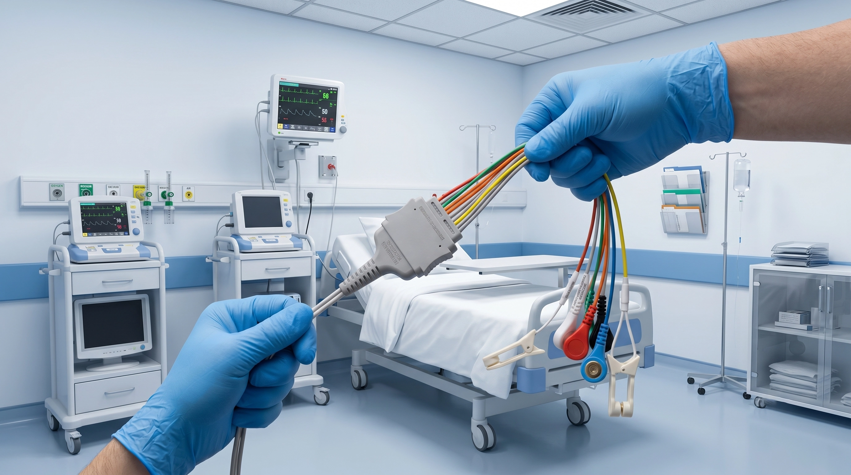
To help an engineering team evaluate a custom cable efficiently, provide as much of the following information as possible:
Intended application and device model
Signal-acquisition or stimulation function
Electrode type and patient-contact location
Connector drawings, photos, samples or part numbers
Confirmed pinout and channel configuration
Cable length, number of leads and branching structure
Shielding and electrical requirements
Jacket material, color and flexibility requirements
Cleaning, reuse and environmental conditions
Labeling, packaging and traceability requirements
Estimated prototype quantity and annual demand
Target market and applicable compliance requirements
Even a clear device-interface photo or an existing cable sample can reduce repeated communication and accelerate the initial engineering review.
Heymed Medical provides OEM and ODM development for medical electrode cables, medical lead wires and healthcare connectivity assemblies. Our capabilities cover ECG and EEG cables, surface EMG connections, TENS and EMS lead wires, tVNS and taVNS ear-electrode cables, patient-monitoring leads and custom device interfaces.
Support may include connector and pinout evaluation, cable-structure design, material selection, prototype development, overmolding, labeling, electrical and mechanical testing, and scalable manufacturing under an ISO 13485 quality management system.
Final performance, safety and regulatory compliance must be confirmed for the complete medical device and its intended use.
The best medical electrode cable is not selected by connector shape or cable appearance alone. It is selected by matching the electrode, electrical function, device interface, patient-contact conditions, mechanical environment and verification requirements.
For a custom medical electrode cable or lead-wire project, share your application, device interface, pinout, cable requirements and expected quantity with the Heymed Medical engineering team for an initial technical review.
Work with Heymed Medical on OEM/ODM development and controlled manufacturing for tVNS and taVNS products, EEG electrodes, medical lead wires, custom cable assemblies, and medical docking and charging products—from engineering samples and validation to volume production.
Tell our engineering team about your product application, device interface, performance targets, compliance needs, and expected quantity. We will review your information and contact you to discuss technical feasibility, customization options, and recommended next steps.
Tip: A drawing, device interface photo, pinout diagram, or reference sample can help our engineering team evaluate your project more accurately and efficiently.
 Search