Explore product updates, engineering guides, application insights, and exhibition news from Heymed Medical, covering medical cable assemblies, EEG electrodes, neurostimulation accessories, and OEM/ODM development.
A buyer can often start a custom ear clip electrode project with only a photo or reference sample, but a production-ready design requires more than matching the clip shape. The host-device interface, ear-contact position, connector, pinout, cable construction, materials, strain relief, identification and sample-approval criteria all need to be considered as one system.
For OEM buyers evaluating a custom ear electrode manufacturer or supplier, the fastest way to shorten the first engineering review is to separate what is already confirmed from what still needs to be defined. A clear input package reduces repeated questions, unnecessary sample rounds and the risk of approving a visually correct but electrically incompatible assembly.
The information below does not need to be complete before the first discussion. However, providing as many confirmed items as possible gives the engineering team a clearer basis for reviewing the project and identifying what still needs to be defined.
| Information to Provide | Why It Matters | Useful Input Format |
|---|---|---|
| Host device and electrode role | Defines what the electrode is expected to do within the system. | Device type, system information or short written description |
| Ear position and contact arrangement | Contact location influences clip geometry, contact size and orientation. | Placement drawing, marked photo, contact count or bilateral requirement |
| Reference product or sample | Helps confirm structure, dimensions and assembly direction. | Existing sample, clear photos, 2D/3D drawing or dimensioned sketch |
| Connector and mating interface | Connector appearance alone does not confirm mechanical or electrical compatibility. | Connector part number, mating dimensions, socket drawing or approved sample |
| Pinout / polarity / channel definition | Internal wiring must correspond with the host-device definition. | Pin map, polarity, channel assignment or wiring diagram |
| Cable requirements | Cable construction affects routing, flexibility, signal requirements and strain at the clip. | Overall length, branch length, conductor needs, shielding, jacket, color and cable direction |
| Material and use conditions | Materials should be reviewed according to the expected use and project specification. | Contact material, clip material, reuse requirements and cleaning approach |
| Identification and packaging | Marking may be needed for left/right, channels, polarity or product identification. | Label, logo, product code, channel marking and packaging requirements |
| Sampling and volume information | Prototype quantity and expected volume may affect the recommended manufacturing approach. | Sample quantity, estimated production volume and expected project timing |
For an OEM ear clip electrode project, the most useful first input is the host-device context. The same-looking ear clip can serve different system roles, and connectors with similar external shapes may use different internal wiring.
Product teams should identify the device type, assigned channel or electrode role, number of contacts, single- or bilateral configuration, expected ear position and cable routing before selecting a mechanical reference.
If the project is replacing an existing accessory, providing the original sample together with the device-side connector information can significantly reduce uncertainty during the first engineering review.
This helps avoid a common sourcing problem: approving a sample because the clip and connector look correct while the internal wiring, contact position or mechanical fit does not match the host system.
The ear is not a flat or standardized interface. The expected contact position affects clip opening, jaw geometry, contact height, contact area, approach angle and cable direction.
A marked wearing photo or simple placement drawing can therefore provide more useful engineering information than a general description such as “earlobe clip” or “auricular electrode.”
For a new structure, provide the required number of conductive areas, approximate contact position, left/right orientation and any dimensional restrictions created by the device or wearable structure.
Clip force should not be specified in isolation. Contact area, spring or hinge structure, opening range and cable pull should be reviewed together so that the mechanical design works with the intended contact position.
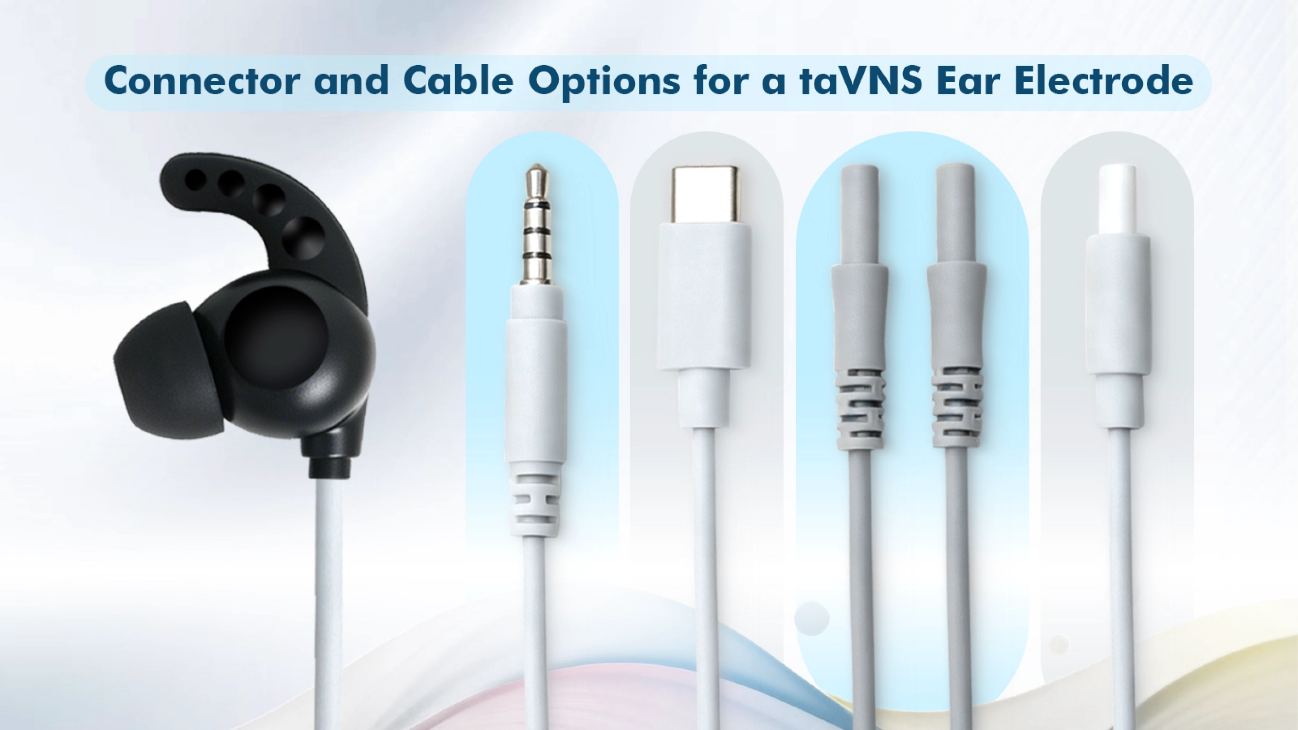
Connector selection should be based on mating dimensions, terminal definition and host-device requirements rather than the common name or appearance of the plug alone.
Two connectors that appear identical can use different pin assignments, polarities or internal wiring. For this reason, the most useful input is a connector part number or dimensional drawing together with the pinout or wiring definition.
If these documents are unavailable, provide a device-side connector photo, basic measurements and a known working sample where possible. The final electrical definition should be confirmed before the sample is released as the approved reference.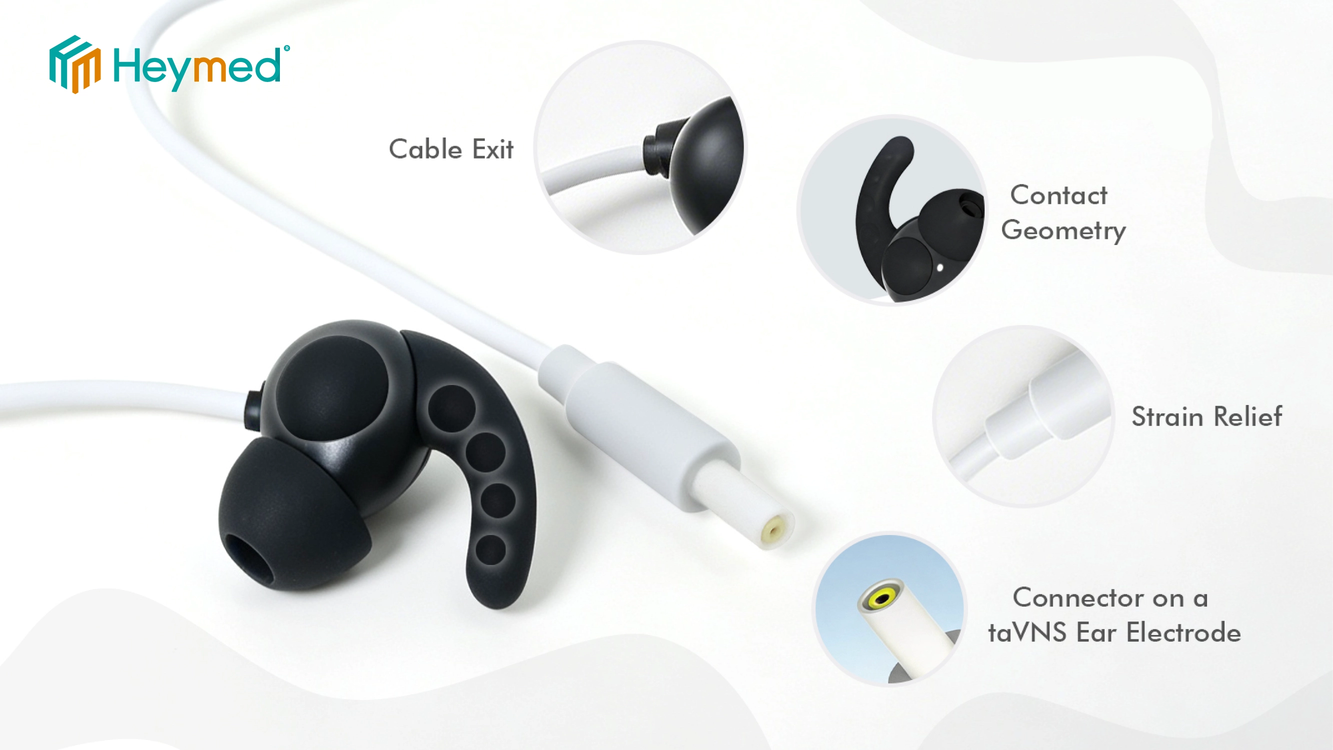
Cable length is only one part of the specification. Depending on the host system and application, the project may also need to define conductor count, flexibility, shielding, branch construction, jacket material, color, strain relief, overmolding and cable exit direction.
For multi-lead or bilateral assemblies, branch lengths and channel identification should be included in the controlled drawing so that prototype samples and later production use the same reference.
For signal-sensitive systems, shielding should be selected according to the electrical architecture and device requirements rather than added automatically to every cable.
Material selection depends on the conductive-contact concept, expected use, cleaning or replacement method and the documentation required for the finished device.
The clip body, conductive contact, cable jacket, colorants and overmold materials should therefore be reviewed against the agreed project specification rather than selected only from a general catalog description.
If the accessory is intended for repeated use, provide the expected cleaning approach and relevant use conditions. If left/right, polarity or channel identification matters, define the required color, label, mark or product code before the specification is released.
Many custom projects begin before the customer has a finished production drawing. An initial engineering review can usually start with a clear product photo, a reference sample, host-connector information and a short description of the intended configuration.
Heymed Medical can then identify which items are already confirmed and which still need clarification before sampling. Typical open points include ear-contact position, clip dimensions, connector mating, pinout, cable structure, strain relief and identification.
The purpose of the first review is not to require every specification from the buyer at the beginning. It is to convert the available information into a clear list of controlled engineering inputs.
An existing Heymed Medical conductive silicone ear clip electrode can be used as a structural reference when a project requires a compact ear-worn contact with an integrated cable assembly.
Depending on the new project, some mechanical elements may be retained while the connector, wiring, cable length, cable construction, color or identification is changed.
A reference product should not, however, be treated as universally compatible. The host-device interface, pinout, contact position and other project-specific requirements still need to be confirmed before a derivative sample is approved.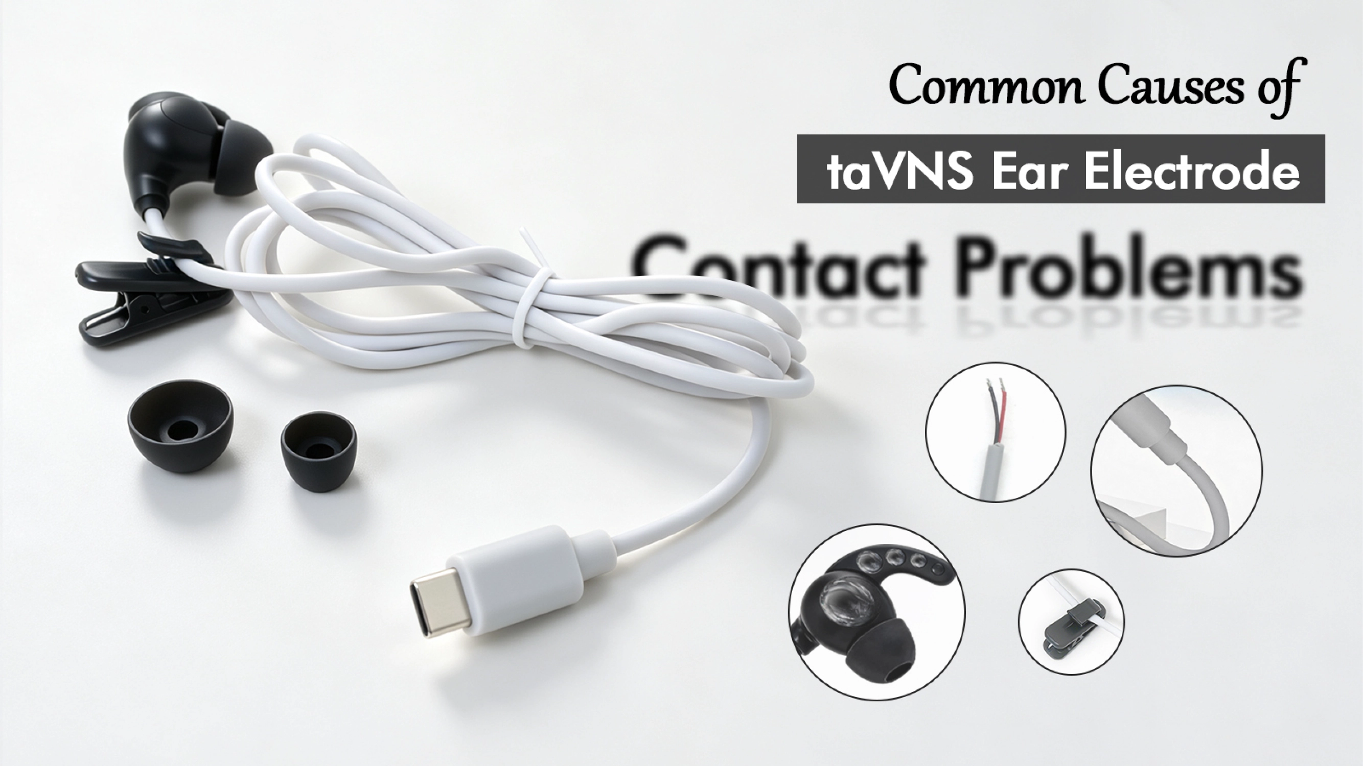
A practical custom project normally moves from requirement review to engineering clarification, drawing or wiring confirmation, sample production, customer evaluation and final specification release.
The exact number of sample rounds depends on the project. Before production, however, the approved reference should clearly define the critical dimensions, connector, pinout, cable construction, materials, identification and inspection requirements that apply to the finished assembly.
Production acceptance should follow the approved sample, drawing and agreed specification rather than a general product description.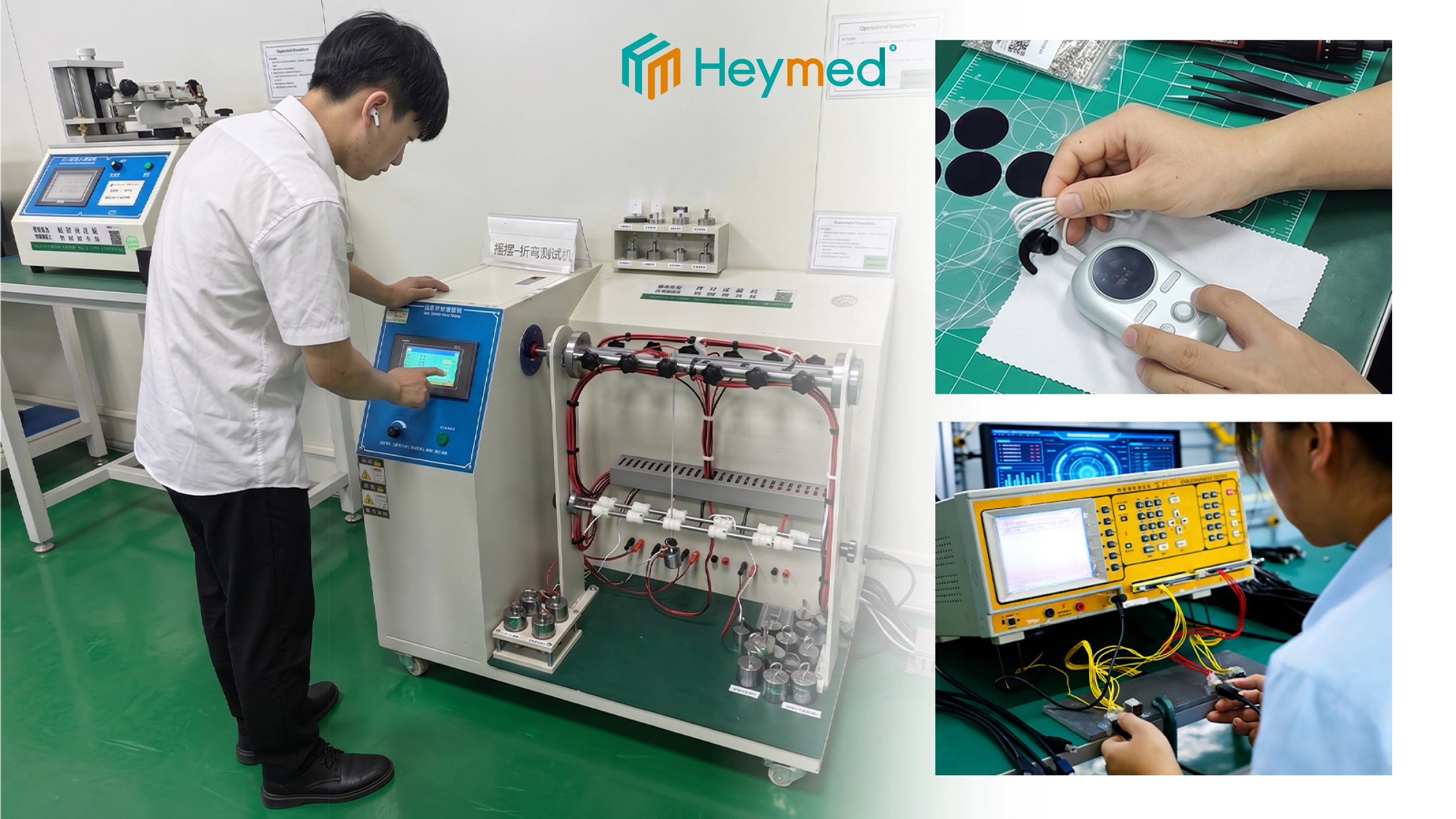
For a more efficient first review, send a short project brief containing the host-device type, intended ear-contact function, reference photo or sample, connector information, pinout, cable length, major material or use requirements, prototype quantity and estimated production volume.
If some information has not yet been decided, mark it as “to be confirmed” rather than guessing. The engineering team can then separate confirmed inputs from the items that need to be resolved before sampling.
If the project also involves a device-side harness, adapter or multi-connector lead, the electrode can be reviewed together with Heymed Medical custom medical cable assemblies so that connector mating, pinout and cable construction are considered as one complete interface.
Yes. A clear photo can be enough for an initial review, especially when it shows the clip, connector and overall cable. Before sample approval, however, the mating interface, wiring or pinout, contact position and critical dimensions still need to be confirmed.
No. A drawing is helpful but not mandatory for the first discussion. A working sample, marked photo, connector information and a short project description can be used to identify the missing engineering inputs.
Not safely. The same connector housing can use different terminals, pin assignments or internal wiring. The mating dimensions and electrical definition should be checked against the actual host device.
They can be reviewed as one assembly. The feasible changes depend on the required contact structure, mechanical limits, connector, pinout, cable construction, material requirements and expected production volume.
The document package is project-specific. Drawing and specification control, inspection records and other requested documents should be agreed during the project review. Documents that are not included in the confirmed project scope should not be assumed.
Send Heymed Medical your host-device information, reference photo or sample, connector and pinout details, and basic cable requirements. If some inputs are still open, our engineering team can help identify the points that need to be confirmed before sampling.
Send Your Drawing or SampleWork with Heymed Medical on OEM/ODM development and controlled manufacturing for tVNS and taVNS products, EEG electrodes, medical lead wires, custom cable assemblies, and medical docking and charging products—from engineering samples and validation to volume production.
Tell our engineering team about your product application, device interface, performance targets, compliance needs, and expected quantity. We will review your information and contact you to discuss technical feasibility, customization options, and recommended next steps.
Tip: A drawing, device interface photo, pinout diagram, or reference sample can help our engineering team evaluate your project more accurately and efficiently.
 Search